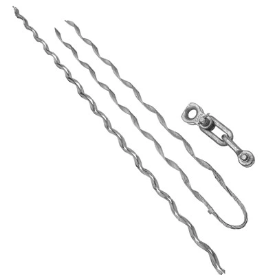
Key Benefits at a Glance
Rapid Deployment
Single-person installation in under 10 minutes without specialized equipment
01
Anti-Slip Engineering
Precision helical design with reinforced wedge blocks ensures zero cable migration
02
Universal Compatibility
Accommodates Φ8-20mm ADSS cable diameters with single and dual-jacket configurations
03
Weather-Proven Durability
UV-stabilized materials withstand -40°C to +70°C, salt spray, and high-voltage environments
04
Global Certification
Complies with IEEE, IEC, and ASTM standards for telecommunications infrastructure
05
Technical Specifications and Performance Data
Product drawing



Standard Model Range
| Model Series | Cable Diameter (mm) | RTS Capacity (%) | Body Material | Wedge Composition | Operating Temp (°C) | Unit Weight (kg) |
|---|---|---|---|---|---|---|
| ADC-810 | 8.0 - 10.0 | ≥95 | GF-Nylon 66 | TPE/Shore A80 | -40 to +70 | 0.65 |
| ADC-1012 | 10.0 - 12.0 | ≥95 | GF-Nylon 66 | TPE/Shore A80 | -40 to +70 | 0.75 |
| ADC-1214 | 12.0 - 14.0 | ≥95 | GF-Nylon 66 | TPE/Shore A82 | -40 to +70 | 0.85 |
| ADC-1416 | 14.0 - 16.0 | ≥95 | GF-Nylon 66 | TPE/Shore A82 | -40 to +70 | 0.95 |
| ADC-1618 | 16.0 - 18.0 | ≥95 | Aluminum Alloy | TPE/Shore A85 | -40 to +70 | 1.15 |
| ADC-1820-HD | 18.0 - 20.0 | ≥95 | Aluminum Alloy | TPE/Shore A85 | -40 to +70 | 1.35 |
Heavy-Duty Series
| Model Series | Cable Diameter (mm) | RTS Capacity (kN) | Armor Rod Length (mm) | Suitable Span (m) | Max Tensile Load |
|---|---|---|---|---|---|
| ADC-1214-LS | 12.0 - 14.0 | 12 | 1200 | 400-800 | 70 kN |
| ADC-1618-LS | 16.0 - 18.0 | 18 | 1400 | 600-1000 | 100 kN |
| ADC-2024-XHD | 20.0 - 24.0 | 24 | 1600 | 800-1200 | 160 kN |
Final Solution
Main Body Construction
Glass-Filled Nylon 66
Tensile strength 85 MPa (ASTM D638)
UV stabilizer content 2.5%
Flame rating UL94 V-2
Aluminum Alloy 6061-T6
Yield strength 240 MPa
Corrosion protection via Type II anodizing
Anodizing thickness 10-15μm
Wedge Block Materials
Thermoplastic Elastomer (TPE)
Shore A hardness 80-85
Compression set <15% (22 hrs @ 70°C per ASTM D395)
Internal grip pattern
Diamond-tooth configuration
0.5mm tooth height
2mm pitch spacing
Suspension Hardware
304 Stainless Steel
Tensile strength 515 MPa minimum
Salt spray resistance >500 hours (ASTM B117)
Hot-dip galvanized options
Zinc coating thickness 70-85μm
Compliant with ASTM A153
Surface Treatment
Corrosion Protection
All metal components undergo specialized surface treatments to ensure long-term corrosion resistance in harsh environmental conditions:
Type II Anodizing
Aluminum components receive Type II anodizing treatment creating a protective oxide layer 10-15μm thick, providing excellent corrosion resistance and surface hardness.
Hot-Dip Galvanizing
Carbon steel components undergo hot-dip galvanizing per ASTM A153, with a zinc coating thickness of 70-85μm for superior corrosion protection in industrial and coastal environments.
UV Stabilization
Polymer components incorporate 2.5% UV stabilizer content to prevent degradation from prolonged sun exposure, ensuring performance retention in direct sunlight applications.
Surface Finish Specifications
Aluminum Components
Anodize Thickness:10-15 μm
Color:Natural
Hardness:≥300 HV
Salt Spray Resistance:≥1000 hours
Stainless Steel Components
Surface Finish:#4 Brush
Passivation:Citric Acid
Salt Spray Resistance:≥500 hours
Corrosion Grade:304/316
Polymer Components
UV Stabilizer:2.5% Content
Flame Rating:UL94 V-2
Color Stability:ΔE < 3 (5000 hrs)
Weathering Resistance:ISO 4892-3

Core Advantages
The ADSS dead-end clamp represents a paradigm shift in how telecommunications providers approach cable termination at tower and pole endpoints. Unlike traditional metallic gripping systems that risk fiber damage through compression stress, our engineered solution delivers optimal load distribution while maintaining signal integrity across extreme environmental conditions.
Broad Application Versatility
Challenge:
Network operators frequently encounter inconsistent cable specifications across multi-vendor deployments, leading to inventory complexity and installation delays.
Solution:
Our modular ADSS dead-end clamp architecture supports an extensive cable diameter range from 8mm to 20mm through interchangeable wedge inserts. A single technician can adapt the termination hardware on-site by selecting the appropriate insert configuration, eliminating the need for multiple clamp models.
This versatility reduces warehouse stock by 60% while ensuring compatibility with both single-jacket MDPE (Medium-Density Polyethylene) and dual-jacket AT (Anti-Tracking) cable constructions commonly deployed in high-voltage corridors.
Industry-Leading Holding Strength
Challenge:
Conventional compression clamps concentrate radial forces at localized points, creating micro-fractures in the cable jacket and potentially compromising fiber geometry under sustained tension loads.
Solution:
The helical preformed rod design of our ADSS dead-end clamp distributes gripping forces across 360-degree contact zones extending 600-800mm along the cable length. This engineering approach achieves holding capacity exceeding 95% of the cable's Rated Tensile Strength (RTS) without inducing harmful stress concentrations.
Field validation demonstrates performance retention after 500 thermal cycles (-20°C to +60°C) and sustained exposure to 80 mph wind loads combined with 12mm radial ice accumulation.
Accelerated Installation Efficiency
Challenge:
Labor costs constitute 40-50% of aerial fiber deployment budgets, with traditional dead-end installations requiring two-person crews and hydraulic crimping tools.
Solution:
Our tool-free ADSS dead-end clamp utilizes a self-aligning cone body with pre-assembled plastic wedge blocks that engage through simple hand pressure.
Installation sequence requires only three steps:
- Mark cable position
- Slide clamp assembly onto cable
- Apply tension release and secure mounting hardware
Certified installers complete terminations in 8-12 minutes versus 25-30 minutes for bolted alternatives, reducing crew deployment time by 65% on projects spanning 50+ poles.
Environmental Resilience
Challenge:
Outdoor fiber optic infrastructure must endure decades of UV radiation, moisture intrusion, chemical exposure, and thermal cycling without degradation that compromises mechanical or dielectric performance.
Solution:
Material specifications for the ADSS dead-end clamp incorporate UV-stabilized glass-reinforced nylon for the main body housing (tensile strength 85 MPa), 304 stainless steel suspension hardware (corrosion resistance per ASTM B117 salt spray testing), and thermoplastic elastomer wedge inserts engineered for temperature stability across -40°C to +70°C operating ranges.
Independent laboratory validation confirms zero performance degradation after 2000-hour accelerated aging protocols simulating 25-year field exposure in coastal and industrial atmospheres.
Application Scenarios
The ADSS dead-end clamp serves as the primary termination interface across diverse network architectures, providing secure anchoring while accommodating the mechanical demands of various aerial deployment configurations.
Primary Application Environments

Terminal Poles
Single-clamp configuration anchors cable at network origination or termination points. Typical deployment includes one clamp unit per terminal structure with direct connection to pole-mounted hardware via thimble-clevis assemblies.

Angle and Corner Towers
Directional changes exceeding 15 degrees require double-clamp installations (one per cable direction) to balance unequal longitudinal forces. The ADSS dead-end clamp's flexible bail allows mounting at offset angles up to 30 degrees.

Tension Structures
Intermediate support points along extended cable routes (>800m between splice points) employ dual clamp configurations to maintain design tension levels while providing access for future cable sectionalizing.

Crossing and Transition Points
Highway overpasses, river crossings, and utility right-of-way transitions demand enhanced mechanical security. Heavy-duty ADSS dead-end clamp variants with reinforced structural rods accommodate these specialized applications.
Cable Compatibility Guidelines

Single-Jacket ADSS Cables
Standard clamp configuration accommodates MDPE (Medium-Density Polyethylene) jacketed cables with outer diameters ranging from 8mm to 16mm.
These cables typically operate in medium-voltage environments (<69 kV) where electric field intensity remains below corona inception thresholds. Select wedge inserts based on precise cable diameter measurements taken at room temperature (20°C ±2°C).
Dual-Jacket (AT) ADSS Cables
High-voltage applications (>69 kV) require Anti-Tracking jacket constructions with specialized electrically conductive outer layers.
The ADSS dead-end clamp accommodates these enhanced cable designs through diameter ranges of 12mm to 20mm using oversized wedge configurations. Critical specification: verify jacket material compatibility-AT jackets must not contact bare metal hardware components to prevent tracking degradation.

Armored and Enhanced Strength
Cables incorporating peripheral aramid yarn reinforcement or central FRP (Fiber Reinforced Plastic) strength members demand careful clamp selection.
Consult engineering tables matching cable construction type to appropriate wedge hardness ratings (Shore A durometer values between 70-85 for standard applications).
Structural Limitations and Design Boundaries
Minimum Angle Restrictions
The ADSS dead-end clamp maintains specified grip performance at installation angles between 0-5 degrees from line direction. Installations exceeding 5-degree deflection angles require specialized hardware configurations to prevent lateral slippage under dynamic wind loading.
Tension Range Parameters
Design tension should remain within 20-50% of cable RTS during normal operating conditions. The clamp's mechanical advantage allows temporary installation tensions up to 600 lbf (2.7 kN) during pulling operations, but sustained working loads must not exceed manufacturer-specified limits.
Prohibited Applications
The ADSS dead-end clamp is engineered exclusively for cable termination functions and must never serve as lifting equipment for personnel safety applications, temporary cable support during construction phases, or emergency backup restraint systems.
Step-by-Step Selection Process
successful cases
Choose the plan that suits you best.
Cable Diameter Measuremer
Using a precision caliper, measure cable outer diameter at three points spaced 120 degrees around circumference. Average the measurements and select clamp model accommodating this dimension with ±0.5mm tolerance.
Note: Temperature-compensate measurements taken outside 15-25°C ambient range (ADSS cables expand ~0.2mm per 10°C temperature increase).

Jacket Type Verification
Identify cable construction from manufacturer documentation:
Single-jacket (MDPE): Standard wedge configuration
Dual-jacket (AT): Specify "DJ" suffix requiring enhanced grip inserts
Armored variants: Consult engineering for special-order configurations
Holding Strength Calculation
Retrieve cable RTS value from specification sheet. Calculate required clamp capacity using formula:
Clamp Rating = Design Tension ÷ Safety Factor
Where Safety Factor = 1.5 for normal conditions, 2.0 for high-wind/ice zones
Verify selected ADSS dead-end clamp model provides ≥95% RTS retention per published load tables.
Accessory Component Selection
Standard installation requires:
Thimble-clevis assembly (TC series): 12-20 kN capacity
U-bolt mounting bracket (UB series): Match pole diameter
Extension link (optional): For offset mounting configurations
Anti-rotation locknut: Stainless steel M16 or 5/8" hardware
Installation Overview
Pre-Installation Preparation
Cable Surface Preparation
Remove any dirt, ice, or contamination from the clamping zone using lint-free cloths moistened with isopropyl alcohol. Avoid touching cleaned areas with bare hands-skin oils reduce friction coefficients by up to 20%.
Hardware Component Verification
Unpack the ADSS dead-end clamp and inspect for intact cone body, properly seated wedge blocks, flexible bail condition, and complete fastener sets.
Structural Attachment Point Assessment
Confirm pole or tower mounting hardware can withstand 2× the anticipated working load. Wooden poles require through-bolt installations with backing plates.
Clamp Assembly and Engagement
Positioning and Alignment
Slide the opened ADSS dead-end clamp body onto the cable, aligning the longitudinal axis with the cable's centerline. The tapered cone opening should face the direction of cable tension.
Wedge Block Installation
Insert the lower wedge block first, ensuring the diamond-tooth grip pattern contacts the cable jacket. Align the upper wedge block and press firmly until both halves mate with the cone body's internal taper.
Tension Application
While maintaining axial alignment, apply gradual tension to the cable using manual pulling force or a cable tensioner set to 30-50% of design tension.
Final Securing
Bail Connection and Load Transfer
Attach the flexible bail to the thimble-clevis assembly, ensuring the connection pin fully engages the clevis body. Torque the securing bolt to manufacturer specifications.
Post-Installation Inspection Checklist
- Wedge blocks remain fully inserted without gaps
- Cable jacket shows no visible damage
- Bail angle does not exceed 5 degrees from cable centerline
- All fasteners tightened to specified torque values
- Minimum bend radius maintained
FAQ
Q: How do I determine the correct clamp model when cable diameter falls between size ranges?
A: When measured diameter approaches the upper boundary of one model and the lower boundary of the next larger size, select the larger clamp and use the corresponding small-diameter wedge insert. This approach ensures adequate compression without over-tightening. Example: For a 13.8mm cable, choose the ADC-1416 model with 14mm wedge configuration rather than stretching the ADC-1214 to its maximum capacity.
Q: What does "≥95% RTS holding capacity" mean in practical terms?
A: Rated Tensile Strength (RTS) represents the cable's breaking load under controlled laboratory conditions. A clamp rated at ≥95% RTS will maintain grip integrity up to 95% of that breaking threshold without slippage. For a cable with 10 kN RTS, the ADSS dead-end clamp provides secure termination up to 9.5 kN applied tension-well beyond the 4-5 kN typical working loads in most deployments.
Q: What differentiates single-jacket and dual-jacket ordering specifications?
A: Single-jacket cables feature one protective MDPE layer, while dual-jacket (AT) cables incorporate an outer electrically conductive layer for high-voltage environments. The key difference: dual-jacket configurations require wedge inserts with modified grip patterns to prevent damage to the conductive outer layer while maintaining holding strength. Always specify jacket type during ordering to receive appropriate hardware.
Q: Can the ADSS dead-end clamp perform reliably in coastal or industrial polluted environments?
A: Yes-material selection specifically addresses harsh atmospheric conditions. The UV-stabilized nylon body resists degradation from ozone and industrial chemicals, while 304 stainless steel hardware withstands salt spray per ASTM B117 testing (>500 hours exposure without corrosion). For extreme marine environments, upgrade to 316 stainless steel components for enhanced protection. Regular visual inspections every 24 months ensure early detection of any environmental degradation.
Q: Is the clamp reusable if I need to relocate or reposition a cable?
A: The ADSS dead-end clamp employs mechanical wedge compression that permanently conforms to the specific cable surface during initial installation. While the clamp body itself remains intact, the wedge blocks and cable jacket contact zone experience microscopic deformation during first-time engagement. Reuse risks compromised holding capacity due to imperfect re-engagement of these worn surfaces. Best practice: deploy new clamp assemblies for each installation to maintain warranty coverage and performance guarantees.
Engineering Excellence for Critical Infrastructure
For network architects designing next-generation fiber infrastructure, construction managers overseeing large-scale deployment projects, or maintenance teams responsible for existing aerial plant, the ADSS dead-end clamp delivers proven performance that stands the test of time.
Hot Tags: adss dead end clamp, China adss dead end clamp manufacturers, suppliers, factory