Technical Specifications
| Parameter | Value | Description |
|---|---|---|
| Split Ratio | 1×32 | One input port, thirty-two output ports |
| Insertion Loss | ≤16.9 dB | Maximum optical power loss from input to output |
| Insertion Loss Uniformity | ≤1.5 dB | Power variation between output ports |
| Return Loss | ≥55 dB | Measure of signal reflection at connectors |
| Directivity | ≥55 dB | Isolation between output ports |
| Polarization Dependent Loss (PDL) | ≤0.3 dB | Loss variation with polarization state |
| Wavelength Range | 1260–1650 nm | Operates across O, C, and L bands |
| Wavelength Dependent Loss (WDL) | ≤0.5 dB | Loss variation across operating wavelength |
| Temperature Dependent Loss (TDL) | ≤0.5 dB | Loss variation across operating temperature |
| Operating Temperature | -40 to +85 °C | Wide range for various deployment environments |
| Storage Temperature | -40 to +85 °C | Temperature range for storage |
| Relative Humidity | 0–95% (non-condensing) | Humidity tolerance |
| Fiber Type | G.657A1 | Bend-insensitive singlemode fiber |
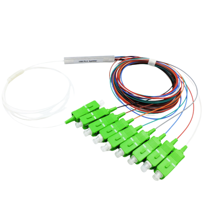
| Connector Type | SC/APC | Angled Physical Contact for low reflection |
| Pigtail Length | 1.5m standard | Custom lengths available (0.5m–3.0m) |
| Pigtail Diameter | 2.0mm | Standard buffer size for indoor applications |
| Dimensions | 120×80×18 mm | Compact cassette form factor |
| Weight | Approx. 100g | Lightweight design for easy handling |
| Material | ABS | Durable, impact-resistant housing |
| Compliance | Telcordia GR-1209, GR-1221 | Telecom industry standards |
Features

Standardized Cassette Form Factor
The cassette PLC splitter conforms to industry-standard dimensions recognized by equipment manufacturers, system integrators, and network operators worldwide. The 120×80mm footprint matches LGX adapter panel slots, enabling direct installation into fiber distribution hubs, optical distribution frames (ODF), and rack-mount patch panels without requiring adapter brackets or custom mounting hardware.
This standardization simplifies inventory management-network operators can stock cassette PLC splitters from multiple suppliers while maintaining installation compatibility across their infrastructure. The cassette design also facilitates field replacement and network upgrades; technicians can swap cassette PLC splitters for different split ratios or repair failed units by unplugging connectors and removing mounting screws, typically completing the operation in under five minutes without disturbing adjacent fibers or equipment.
Bend-Insensitive Fiber Technology
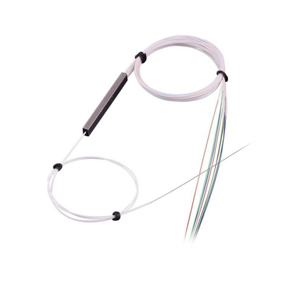
All input and output pigtails on this cassette PLC splitter use G.657A1 compliant bend-insensitive singlemode fiber, engineered to maintain low attenuation through bend radii as tight as 10mm. This characteristic proves essential in high-density cassette installations where multiple cassette PLC splitters mount adjacently in shared frames, creating congested fiber pathways between cassette modules and patch panels.
Traditional G.652D fiber would suffer significant macrobending loss when routed through tight corners, cable tie points, and narrow cable management channels common in equipment racks. Installation teams can route cassette PLC splitter pigtails through compact pathways without compromising optical performance, reducing installation time by eliminating the need for generous service loops and elaborate fiber management accessories that consume valuable rack space.


Low Insertion Loss with Uniform Distribution
The PLC chip within this cassette PLC splitter delivers maximum insertion loss of 16.9 dB across all 32 output ports, with port-to-port uniformity maintained within 1.5 dB. This tight uniformity specification ensures that subscribers connected to any output port experience similar optical power levels, simplifying link budget calculations and enabling consistent service quality across the entire serving area.
Network planners can confidently design FTTx topologies knowing the cassette PLC splitter will not introduce significant power imbalances requiring per-port adjustments or limiting maximum transmission distances for specific subscribers. The low insertion loss preserves valuable optical power budget for longer fiber runs, additional cascaded cassette PLC splitters in multi-stage architectures, or margin against component aging over the network's operational lifetime.
Factory-Terminated Plug-and-Play Connectivity
Every cassette PLC splitter ships with factory-terminated SC/APC connectors on all ports, eliminating field splicing operations that consume installation time and introduce quality variability. Installers simply plug the cassette PLC splitter input connector into the feeder fiber from the OLT or upstream distribution point, mount the cassette into the LGX frame or rack chassis, then connect output fibers directly to patch panels, splice closures, or downstream cassette PLC splitters in cascaded configurations.
The angled physical contact (APC) polish geometry provides superior return loss performance (≥55 dB) compared to ultra-physical contact (UPC) connectors, critical for preventing Rayleigh backscatter and Fresnel reflections that disrupt PON burst-mode protocols and video overlay signals.

Connectivity Solutions and Network Topologies

Centralized Split Architecture
In centralized split deployments, high-ratio cassette PLC splitters such as 1×32 or 1×64 models are installed in the central office, headend equipment room, or main distribution frame (MDF) location. The OLT connects to the cassette PLC splitter input through a short fiber jumper, and all 32 or 64 output fibers from the cassette run through the outside plant to individual subscriber locations or building entrance terminals.
This topology minimizes the number of passive components in the field, simplifying inventory management, reducing potential failure points, and keeping critical distribution infrastructure within controlled, accessible environments.
Key Benefits
- Reduced field components and potential failure points
- Simplified inventory management
- Centralized maintenance and troubleshooting
- Ideal for high-density urban areas
- Lower initial deployment costs
Distributed Split Architecture
Distributed or cascaded split topologies employ multiple cassette PLC splitter stages to extend PON reach, increase flexibility, and optimize fiber plant utilization. A first-stage 1×4 or 1×8 cassette PLC splitter near the OLT divides the optical signal toward multiple serving areas, fiber distribution hubs (FDH), or neighborhoods.
Second-stage 1×8 or 1×16 cassette PLC splitters located in street cabinets, building basements, or outdoor fiber access terminals complete the power division to individual subscribers. For example, a 1×8 primary cassette PLC splitter combined with eight 1×8 secondary cassette PLC splitters creates an effective 1×64 total split ratio.
Key Benefits
- Extended PON reach to remote areas
- Optimized fiber plant utilization
- Phased deployment capability
- Reduced fiber count between central office and remote hubs
- Flexible expansion as subscriber density increases

Application Scenarios

FTTx and FTTH Access Networks
Deploy cassette PLC splitters in central offices, remote terminals, or fiber distribution hubs to distribute GPON/EPON signals from OLTs to residential subscribers, enabling cost-effective gigabit internet service delivery.

Data Center Interconnects
Install cassette PLC splitters in meet-me rooms, cross-connect facilities, and equipment distribution areas to create optical monitoring taps and test access points for mission-critical data center links.

Passive Optical LAN
Integrate cassette PLC splitters into building MDFs and IDFs to create Passive Optical LAN architectures serving office floors and workspace areas without active switches at every location.

Multi-Tenant Commercial Buildings
Deploy cassette PLC splitters in telecommunications rooms and riser closets to provide flexible fiber distribution to multiple tenants, enabling rapid connectivity provisioning.

PON-Based Campus Networks
Use cassette PLC splitters to extend fiber connectivity across university campuses, hospital complexes, government facilities, and corporate office parks connecting distributed buildings.

CATV and Video Overlay Services
Support analog and digital video distribution at 1550–1560 nm using the same cassette PLC splitter infrastructure carrying data traffic, enabling triple-play service offerings.
Hot Tags: cassette plc splitter, China cassette plc splitter manufacturers, suppliers, factory