What Is EDFA?
EDFA is an optical amplifier that uses a section of erbium-doped fiber to amplify light signals directly in the optical domain. Traditional repeaters require optical-to-electrical-to-optical (O-E-O) conversion at every stage; EDFA skips all of that. The signal stays as light from start to finish - which preserves bandwidth, cuts latency, and strips out a whole layer of network complexity.
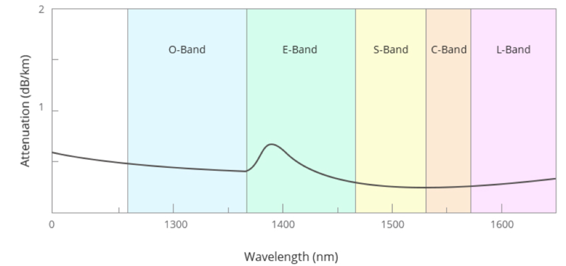
It operates in the C-band (1530–1565 nm) and L-band (1565–1625 nm), right in the lowest-loss transmission windows of silica fiber. That spectral overlap is no coincidence - it's the reason EDFA became the default amplifier in long-haul networks, and the reason WDM and DWDM systems work the way they do. A single EDFA can boost dozens or even hundreds of wavelength channels traveling through one fiber at the same time.
EDFA Problem It Solves
Optical signals lose strength as they travel through fiber. Attenuation, splice losses, connector losses - it all adds up. Before EDFA, the only option was to place electronic regenerators along the route. These devices converted light to electricity, cleaned up the signal, re-amplified it, and converted it back to light. Every regenerator was expensive and format-specific: it could only handle one data rate and one modulation scheme. If you wanted to scale a WDM system, you had to multiply regenerators by the number of channels. The cost and complexity scaled brutally.
The breakthrough came in 1987, when researchers showed that erbium-doped fiber could amplify signals near 1550 nm through stimulated emission. Two years later, the first diode-pumped erbium-doped fiber amplifier was validated in a lab, proving the concept could work in real networks. What made this so significant wasn't just the amplification itself - it was that a single EDFA could amplify all wavelength channels in a WDM system at once. No per-channel regeneration. That one capability is what made dense wavelength-division multiplexing economically viable and put terabit-scale submarine cables within reach.
How Does EDFA Work?
The Core Mechanism: Stimulated Emission
EDFA operates on the same principle as a laser - stimulated emission - except it amplifies existing light instead of generating new light.
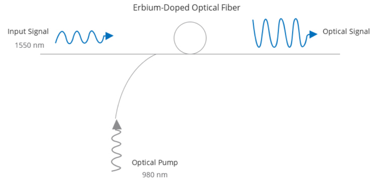
A high-power pump laser (operating at 980 nm or 1480 nm) injects energy into the erbium-doped fiber. Erbium ions (Er³⁺) absorb this pump energy and jump from their ground state to an excited state. Once enough ions are excited, you get population inversion - more ions sitting in the high-energy state than in the ground state. That's the prerequisite for amplification to happen.
Now a weak optical signal near 1550 nm enters the doped fiber. Its photons hit the excited erbium ions, and each interaction triggers an ion to drop back down to the ground state, releasing a new photon in the process. This new photon is identical to the signal photon - same wavelength, same phase, same direction. Multiply that across billions of interactions along the length of the fiber, and the signal comes out the other end significantly stronger.
The amplification is inherently broadband. The erbium gain spectrum spans roughly 30–40 nm in the C-band. That's not a clever engineering workaround - it's baked into the physics of the erbium ion's energy level structure. A single EDFA can handle 40, 80, or even 96 DWDM channels simultaneously because of this.
Key Components Inside an EDFA
A working EDFA module has more going on than just a piece of doped fiber. Five core components work together:
Erbium-doped fiber (EDF) is the gain medium. Fiber length, erbium concentration, and glass composition all shape the gain and noise characteristics. The pump laser supplies the energy to excite erbium ions - its power and stability are what determine the EDFA's gain and noise figure. A WDM coupler merges the pump light and signal light so they propagate through the doped fiber together. Optical isolators at input and output block back-reflections that could destabilize the amplifier or trigger parasitic lasing. And an optical filter strips away out-of-band noise and amplified spontaneous emission (ASE) to keep the output clean.
980 nm vs 1480 nm Pumping - Why Many EDFAs Use Both
The pump wavelength is one of the biggest design decisions in an EDFA, and the two options involve a genuine tradeoff - not just different specs on a data sheet.
980 nm pumping excites erbium ions to a high energy level (E3), which then rapidly relax to the metastable level (E2) through a non-radiative process. That two-step path produces a very clean population inversion and a lower noise figure - typically 1–2 dB better than 1480 nm. For pre-amplifiers where every fraction of a dB in noise matters, 980 nm is what you want.
1480 nm pumping takes a shortcut: it excites erbium ions directly to the metastable level (E2). More energy-efficient, higher achievable output power, but noisier. That makes it the better fit for booster amplifiers where raw power matters more than noise performance.
A lot of high-performance EDFAs don't pick one or the other - they use both. 980 nm pumps in the forward direction to keep noise low, 1480 nm pumps in the backward direction to push output power up. This hybrid configuration is standard in submarine and long-haul terrestrial systems, and for good reason: you get the noise benefit of 980 nm and the power benefit of 1480 nm in a single unit.
Three Types of EDFA and When to Use Each
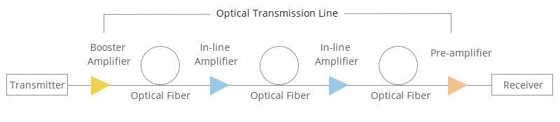
Where an EDFA sits in the optical link determines everything about how it should be designed. The specs that matter for a booster are almost irrelevant for a pre-amplifier, and vice versa.
Booster Amplifier
Goes right after the transmitter. Its job is to push signal power as high as possible before the light enters the fiber span. In DWDM systems, the multiplexer introduces insertion loss that eats into launch power, and the booster compensates for that. The spec that matters most here is saturated output power - typically 16–23 dBm. Noise figure is secondary because the input signal is still strong.
In-Line Amplifier
These sit at intermediate points along the fiber route, usually every 80–100 km, compensating for span loss and keeping the signal above the noise floor. They need high gain (20–30 dB) with decent noise performance. Here's the thing about in-line amplifiers: noise accumulates at every stage. When you're designing the noise budget for a chain of 10, 20, or 100 cascaded EDFAs in a submarine cable, every amplifier's contribution matters. Getting this wrong by even a small margin can mean the difference between a working link and one that doesn't close.
Pre-Amplifier
Sits right before the receiver. By this point, the signal may have crossed hundreds or thousands of kilometers and arrived at very low power - sometimes below -30 dBm. At these levels, ASE noise growth is at its worst. Noise figure is the single most important parameter for a pre-amp. A 1 dB improvement in NF here can directly translate into extended reach or better bit error rate for the whole link.
Key Performance Parameters
Gain
Measured in dB. A gain of 30 dB means the output is 1,000 times stronger than the input. Some EDFA designs can exceed 50 dB, though most commercial units run in the 15–35 dB range. Gain depends on EDF length, pump power, and input signal level. It's not a fixed number - as input power increases, gain compresses due to saturation. Link budget calculations need to account for this.
Noise Figure (NF)
Quantifies how much extra noise the EDFA adds. The theoretical minimum is 3 dB (the quantum limit for a phase-insensitive amplifier at high gain), and commercial EDFAs typically achieve 5–7 dB in small-signal conditions. For pre-amps and cascaded long-haul links, NF is often the first parameter you optimize, because it directly sets the OSNR budget for the entire system.
Saturated Output Power
The maximum output power the EDFA can deliver when the input is strong enough (typically ≥0 dBm) to drive it into saturation. This is the headline number for booster amplifiers. More output power means you can launch more into the fiber, which generally means longer spans between amplifier sites.
Gain Flatness
In a DWDM system with many channels, each channel ideally gets the same gain. The erbium gain spectrum doesn't cooperate - some wavelengths naturally get amplified more than others. Gain flatness measures that variation, usually expressed as peak-to-peak dB across the operating band.
The problem becomes obvious when you cascade amplifiers. Say one channel gets 0.5 dB less gain per amplifier. After ten amplifiers, it's 5 dB weaker. After twenty, it might fall below the receiver's sensitivity threshold entirely. Submarine cable systems and long-haul terrestrial networks deal with this through gain-flattening filters (GFFs) built into the EDFA module, or by tuning the aluminum concentration in the EDF glass to improve the gain spectrum's inherent flatness.
EDFA vs Other Optical Amplifiers
EDFA vs SOA (Semiconductor Optical Amplifier)
SOA uses a semiconductor gain medium instead of doped fiber. It's smaller, cheaper, and can be integrated onto photonic chips - real advantages for metro networks, optical switching, and signal processing. But for long-distance transmission, it doesn't hold up. SOA's gain tops out around 15–25 dB (EDFA can exceed 50 dB), its noise figure runs 7–12 dB (versus EDFA's 5–7 dB), it's polarization-sensitive, and it introduces crosstalk between WDM channels that EDFA simply doesn't.
SOA has its place. EDFA has its place. For backbone DWDM transport, the choice isn't close.
EDFA vs Raman Amplifier
Raman amplification works through a completely different mechanism - stimulated Raman scattering - and it happens inside the transmission fiber itself, not in a separate doped fiber. Because the signal gets amplified gradually along the span instead of all at once, it never drops as low as it would with EDFA-only amplification. The effective noise figure can be lower as a result.
The downsides are real, though. Raman amplifiers demand high pump power (often over 500 mW), deliver modest gain (10–15 dB typically), and add deployment complexity. On the other hand, they're wavelength-flexible in a way EDFA can't match - just shift the pump wavelength to amplify a different band.
These two technologies aren't really competitors. Most ultra-long-haul and submarine systems use both: Raman provides a distributed gain "floor" that keeps the signal from dropping too far into the noise, and EDFA delivers the high-gain concentrated amplification at each repeater. This hybrid approach has become the standard way to push both capacity and reach to their limits.
Where EDFA Is Used Today
Long-Haul Terrestrial Networks
This is where EDFA earns its keep. In backbone networks spanning national or continental distances, EDFAs go in every 80–100 km to fight fiber attenuation. A single fiber optic amplifier carrying 80+ DWDM channels at 100G or 400G per channel depends on a chain of these amplifiers to maintain signal quality over thousands of kilometers. Take EDFA out of the picture, and the economics of high-capacity terrestrial transport collapse.
Submarine Cable Systems
Submarine cables are the harshest environment an EDFA will ever face. A transoceanic cable can stretch beyond 10,000 km with over 100 EDFA repeaters sitting on the ocean floor. These units have to run continuously for 25 years with zero maintenance access. Reliability isn't just a nice-to-have - a failure on the seabed means an expensive ship visit. These EDFAs run with redundant pump lasers and conservative operating margins designed to maximize lifespan above all else.
Data Center Interconnect (DCI)
Hyperscale data centers need high-bandwidth, low-latency links between campuses, and those links often span tens to hundreds of kilometers. EDFA enables coherent 400G and 800G transmission on these DCI routes. With AI training increasingly distributed across multiple facilities, this segment is growing fast.
DWDM Systems
EDFA didn't just become compatible with DWDM - it's what made DWDM practical in the first place. Amplifying 40, 80, or 96 channels simultaneously in one device is what let network operators scale fiber capacity without scaling infrastructure at the same rate. Every DWDM system running today has EDFA in it.
CATV Distribution Networks
Cable TV networks use EDFAs as power amplifiers to boost the optical signal from the headend, pushing it out to a larger subscriber base across a wider coverage area. The high output power of booster-type EDFAs fits this broadcast distribution model well.
Other Applications
EDFA also shows up in fiber amplifier deployments within fiber-based LANs (compensating for distribution losses), military and aerospace communications (where reliability and environmental tolerance are non-negotiable), and emerging quantum communication networks (where amplifying weak signals without electrical conversion has particular value).
How to Choose the Right EDFA
Picking the right EDFA starts with understanding its role in your network. A booster, an in-line amplifier, and a pre-amp have completely different priority stacks - buying a low-noise unit for a booster application is wasting money on a spec that doesn't help you.
Define the role first. Booster means you care about saturated output power. In-line means you're balancing gain against noise. Pre-amp means noise figure is king.
Confirm your operating band. C-band (1530–1565 nm), L-band (1565–1625 nm), or both. C+L EDFAs exist, but availability and performance vary by vendor.
Calculate gain and power requirements from your span loss budget. For a booster, focus on saturated output power. For an in-line amp, make sure gain covers span loss with margin. For a pre-amp, verify the minimum input power it can handle while still hitting acceptable NF.
Evaluate noise figure carefully if you're cascading. Lower NF means more OSNR margin, which means longer reach or better BER. In a chain of amplifiers, even 1 dB of NF improvement compounds across every span.
Check gain flatness - especially for DWDM with high channel counts. The more EDFAs in your chain, the tighter this spec needs to be. A system running 40 channels has different flatness requirements than one running 80.
Factor in the deployment environment. Indoor rack-mount, outdoor cabinet, and subsea are three very different worlds. Operating temperature range, humidity tolerance, mechanical shock rating, MTBF - all of these shift based on where the unit goes. Subsea EDFAs are essentially a different product category from rack-mount units.
FAQ
Q: Can EDFA amplify any wavelength?
A: No. EDFA covers the C-band (1530–1565 nm) and L-band (1565–1625 nm) only. For wavelengths outside that range - like the O-band (1260–1360 nm) used in some short-reach applications - you need a different amplifier technology, such as SOA or Raman.
Q: What's the difference between EDFA and a traditional repeater?
A: A traditional repeater converts the optical signal to electrical, regenerates it, and converts it back to light (O-E-O). EDFA amplifies light directly, with no electrical conversion at any point. That makes it simpler, faster, transparent to data format, and able to handle all WDM channels at once. A repeater would need separate hardware for each channel.
Q: How many EDFAs can you cascade in a single link?
A: That depends on your OSNR budget. Every EDFA adds ASE noise, so signal quality degrades with each stage. Submarine cable systems routinely cascade over 100 EDFAs, but it takes careful management of gain, output power, and gain flatness at every amplifier site to make it work.
Q: Should I use 980 nm or 1480 nm pumping?
A: If noise figure is your priority - pre-amplifiers, long cascaded chains - go with 980 nm. If output power matters more - boosters, high-power applications - 1480 nm is the better choice. Many high-end EDFAs use both: 980 nm forward, 1480 nm backward.
Q: How much does an EDFA cost?
A: It ranges widely. A basic single-channel C-band module might start at a few hundred dollars. A multi-channel unit with built-in gain flattening for DWDM can run several thousand. Submarine-grade EDFAs with enhanced reliability cost significantly more. Output power, noise figure, and channel count all affect pricing - get quotes directly from vendors for anything specific.
Q: What do I do if my EDFA's ASE noise is too high?
A: Check the pump laser power first - degraded output is a common culprit. Make sure the input signal power is within spec, because running below minimum input worsens ASE. Inspect connectors and splices for excess loss. If the unit has been in service for years, pump laser aging is a likely root cause. In cascaded systems, also look at whether gain tilt across the chain is pushing some channels into low-power territory where ASE starts to dominate.
Q: Does EDFA work in CWDM systems?
A: Only partially. CWDM spans a much wider wavelength grid (1270–1610 nm) than DWDM, and EDFA only covers the C and L bands. Channels falling within 1530–1625 nm can be amplified; the rest cannot. Full CWDM band coverage requires combining EDFA with other amplifier types.
Q: How long does an EDFA last?
A: Commercial units are typically designed for 10–25 years of continuous operation. The pump laser is the primary wear component - its gradual degradation is what ultimately limits lifespan. Submarine EDFAs are built to the most stringent standards, with redundant pumps and conservative operating points to ensure decades of service without any maintenance access.