


Silica glass is not equally transparent at every wavelength. Attenuation and chromatic dispersion vary across the near-infrared spectrum, and the wavelength ranges where losses reach practical minima are called optical transmission windows.
The physics behind this is well understood. Rayleigh scattering drops off as 1/λ⁴, meaning longer wavelengths scatter less. Infrared molecular absorption, on the other hand, climbs sharply beyond roughly 1600 nm. The attenuation minimum sits where these two mechanisms cross - near 1550 nm. That crossing point is the reason the C-band occupies the spectral position it does. Separately, a residual OH⁻ ion absorption peak near 1383 nm historically created a dead zone in the spectrum, which is why the O-band and S-band are not contiguous.
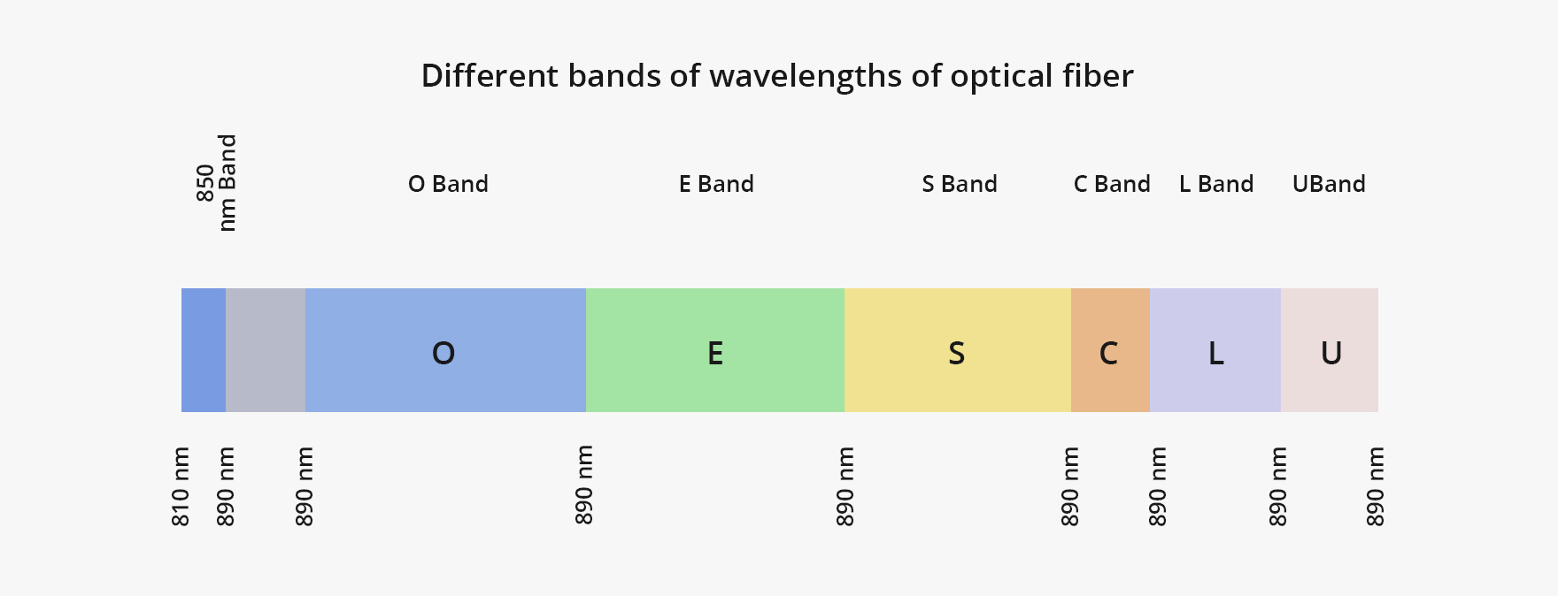
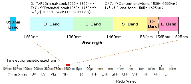
The Seven ITU-T Standardized Bands
| Band | Wavelength Range | Name |
|---|---|---|
| 850 nm | 810–890 nm | 850 nm Band |
| O | 1260–1360 nm | Original Band |
| E | 1360–1460 nm | Extended Band |
| S | 1460–1530 nm | Short Wavelength Band |
| C | 1530–1565 nm | Conventional Band |
| L | 1565–1625 nm | Long Wavelength Band |
| U | 1625–1675 nm | Ultra-Long Wavelength Band |
Four of these carry the bulk of commercial traffic: 850 nm, O-band, C-band, and L-band. The remaining three serve narrower roles.
C-Band (1530–1565 nm)
The C-band is the backbone of modern optical networking. It sits at the bottom of the silica attenuation curve, around 0.19–0.20 dB/km, and its gain window aligns with Erbium-Doped Fiber Amplifiers. This alignment is a coincidence of physics - the emission spectrum of erbium ions in silica glass happens to overlap with the fiber loss minimum - but the entire long-haul transport industry depends on it.
| Parameter | Value |
|---|---|
| Fiber type | G.652, G.654 single-mode |
| Attenuation | ~0.20 dB/km |
| Amplification | EDFA |
| DWDM channel capacity | Up to 96 channels at 50 GHz spacing |
Typical deployments include DWDM long-haul and ultra-long-haul backbone networks, submarine cable systems, 100G/200G/400G/800G coherent transport, and data center interconnect over 80+ km spans. A single fiber pair in C-band DWDM can carry 40–96 channels at 100G or above - aggregate capacity in the tens of terabits per second.
Spectral efficiency on many C-band routes is now approaching the Shannon limit as coherent DSP pushes toward 800G and 1.6T per wavelength. When the math stops working in your favor, the practical response is activating L-band capacity on the same fiber rather than trying to squeeze more bits out of each channel.
O-Band (1260–1360 nm)
The O-band was the first window used commercially for single-mode fiber and continues to dominate medium-distance links. The key property: chromatic dispersion is near zero at 1310 nm in standard G.652 fiber, the point where material dispersion and waveguide dispersion cancel. Optical pulses hold their shape over distance without compensation, which means transceivers can rely on simpler direct-detect architectures - cheaper and lower power than coherent C-band modules.
| Parameter | Value |
|---|---|
| Fiber type | G.652 single-mode |
| Attenuation | ~0.35 dB/km |
| Chromatic dispersion | Near zero at 1310 nm |
| Typical reach | 10–40 km without amplification |
Common applications: 10G LR, 25G LR, 100G LR4 modules; metro Ethernet; enterprise WAN and dark fiber point-to-point; PON upstream (1310 nm, subscriber to OLT); BiDi and CWDM transceivers.
The trade-off is straightforward. O-band attenuation at 0.35 dB/km runs about 75% higher than C-band, and EDFAs do not work at these wavelengths. Beyond 40–80 km you need C-band. Within metro distances, O-band wins on dispersion simplicity and transceiver cost. Semiconductor optical amplifiers and O-band coherent transceivers are in development and could push the usable reach further, but volume deployment is not imminent.
850 nm Band
Inside buildings and data centers, the 850 nm band paired with VCSEL sources and multimode fiber handles the vast majority of short-reach links. Attenuation is high - around 2.5–3.5 dB/km - but when your longest cable run is 300 meters, that number is irrelevant.
| Parameter | Value |
|---|---|
| Fiber type | OM3, OM4, OM5 multimode |
| Attenuation | ~3 dB/km |
| Typical reach | Up to 400 m on OM4 at 100G |
VCSEL-based optics cost significantly less than DFB-laser modules, which is the entire point. Server-to-switch, top-of-rack, campus backbone, 10G/25G/40G/100G SR - all 850 nm territory.
The trend worth tracking: hyperscale data centers are increasingly specifying single-mode fiber in new builds to support 200G and 400G per-lane rates. This is gradually eating into 850 nm's share at the high end. But for the enormous installed base of multimode fiber and for cost-sensitive enterprise networks, the 850 nm band is not going anywhere soon.
L-Band (1565–1625 nm)
The L-band functions as C-band's overflow. It offers the second-lowest attenuation in standard single-mode fiber at roughly 0.22 dB/km and can be amplified with commercially available L-band EDFAs.
| Parameter | Value |
|---|---|
| Fiber type | G.652 single-mode |
| Attenuation | ~0.22 dB/km |
| Amplification | L-band EDFA |
Adding L-band EDFAs and C+L mux/demux at existing amplifier sites roughly doubles the usable fiber bandwidth on infrastructure already in the ground, at a fraction of a new build's cost. This is the first capacity lever operators pull when C-band fills up.
C+L deployments are now standard on major submarine systems and increasingly common on high-traffic terrestrial routes. Combined C+L spectrum has shifted from a nice-to-have to a capacity planning baseline for new long-haul infrastructure, especially as per-wavelength rates climb to 800G.
The Secondary Bands
S-Band (1460–1530 nm)
Today the S-band's main commercial use is PON: GPON and XG-PON use 1490 nm for downstream traffic from OLT to subscribers. Beyond that, S-band is a research target for next-generation S+C+L wideband DWDM. Thulium-doped fiber amplifiers and Raman amplification are candidate gain solutions, but neither is close to matching C/L-band EDFA cost or reliability at production scale. Lab demonstrations exist; large-scale commercial S-band DWDM does not.
E-Band (1360–1460 nm)
The OH⁻ water peak near 1383 nm historically made this band unusable. G.652.D zero water peak fiber eliminates the absorption, and E-band attenuation on ZWP fiber actually drops below O-band levels. The problem is installed base: most fiber in the ground worldwide is legacy G.652.A or G.652.B with the water peak intact. Commercial E-band transceivers and amplifiers remain scarce. Realistically, the E-band only matters in greenfield builds on ZWP fiber where every available CWDM slot is needed.
U-Band (1625–1675 nm)
The U-band carries no data traffic. Its sole function is out-of-band fiber monitoring. OTDR equipment at U-band wavelengths injects test pulses into live fiber, measuring reflections, splice losses, connector quality, and breaks without interrupting active services on other bands.
Choosing the Right Transmission Window
| Requirement | Recommended Band | Reason |
|---|---|---|
| Link under 400 m, multimode fiber | 850 nm | Lowest cost with VCSEL optics; sufficient reach |
| Link 1–40 km, single-mode, no amplification | O-band (1310 nm) | Near-zero dispersion; simpler transceiver design |
| FTTH downstream (PON/GPON) | S-band (1490 nm) | PON standard for OLT-to-subscriber downstream |
| Link over 40 km, or DWDM required | C-band (1550 nm) | Lowest loss; EDFA compatible; highest channel density |
| C-band at capacity, need more channels on existing fiber | L-band | Near-doubles usable spectrum with minimal infrastructure change |
| Fiber health monitoring without traffic disruption | U-band | Out-of-band OTDR diagnostics |
| Multiple wavelengths, metro, no amplification | CWDM across O+E+S+C+L | 20 nm spacing; up to 18 channels; lower cost than DWDM |
Key Decision Constraints
Installed Fiber Type
Multimode fiber (OM3/OM4) confines high-speed links to 850 nm. Legacy G.652.A/B single-mode rules out E-band due to the water peak. The fiber already in the ground is the first constraint - everything else follows from it.
Amplification Requirement
EDFAs work in C and L bands only. Links requiring optical amplification - generally beyond 80 km - must use one of these two bands. Extending O-band beyond 40 km means either electrical regeneration or high-power unamplified coherent transceivers, both of which add cost.
Channel Count and Multiplexing Strategy
CWDM supports up to 18 channels with 20 nm spacing, no amplification, and lower per-channel cost. DWDM packs 40–96+ channels into C-band alone (more with L-band), requires EDFAs, and delivers far greater aggregate capacity. Most metro and enterprise links are well served by CWDM. Backbone, submarine, and large-scale DCI demand DWDM. The crossover point is roughly 8–10 channels or amplified spans beyond 80 km.
Transceiver Cost and Power Budget
850 nm VCSEL optics are the cheapest. O-band DFB-based modules (LR, LR4) sit in the middle. C-band coherent modules carry the highest price and power draw. There is no technical benefit to deploying coherent optics on a 10 km metro link that an O-band LR module handles without difficulty.
How WDM Uses Transmission Windows
Wavelength Division Multiplexing assigns different wavelengths to independent data streams and transmits them simultaneously over one fiber. The transmission windows define the total bandwidth of fiber available for this multiplexing.
CWDM
20 nm channel spacing across O, E, S, C, and L bands. Up to 18 channels. No amplification required over normal metro distances. Uncooled lasers keep costs low. Used in metro networks, sub-80 km data center interconnect, and enterprise dark fiber links.
DWDM
100 GHz or 50 GHz channel spacing within C-band, optionally extended to L-band. 40 channels at 100 GHz or 96 at 50 GHz, each carrying 100G or more. EDFAs required for long spans. Deployed on long-haul backbone, submarine cables, and high-bandwidth fiber interconnects.
The choice between CWDM and DWDM comes down to capacity versus cost. CWDM is cheaper per channel but tops out at 18 channels with no amplification path. DWDM costs more but scales to tens of terabits on a single fiber pair.
FAQ
Q: How do I calculate the link budget to determine if my fiber span needs amplification?
A: A link budget adds up all losses between transmitter and receiver: fiber attenuation per kilometer multiplied by span length, plus splice losses (typically 0.05–0.1 dB each), connector losses (around 0.3–0.5 dB per mated pair), and any margin reserved for aging and repairs (usually 2–3 dB). Compare the total to your transceiver's optical power budget - the difference between transmit power and receiver sensitivity. If the total loss exceeds the power budget, you need either amplification (EDFA in C/L-band) or electrical regeneration.
Q: Does fiber age degrade transmission performance across different bands?
A: Yes. Over years of service, fiber attenuation can increase due to hydrogen ingress, microbending from cable stress, and cumulative exposure to moisture. These effects are wavelength-dependent - longer wavelengths in the L-band and U-band tend to be more sensitive to microbending losses than shorter wavelengths. Additionally, legacy fiber installed before G.652.D standards may see the OH⁻ water peak worsen over time if hydrogen penetration occurs. For networks planned with a 15–20 year lifecycle, it is worth factoring in an aging margin of 0.02–0.05 dB/km when designing link budgets.
Q: Can I run C-band and O-band signals simultaneously on the same fiber?
A: Yes. Since C-band (1530–1565 nm) and O-band (1260–1360 nm) occupy non-overlapping wavelength ranges, they can coexist on a single fiber using wideband WDM couplers or band splitters. A typical scenario is running DWDM long-haul traffic in the C-band while carrying local 10G or 25G LR connections in the O-band on the same fiber strand. The key requirement is proper band-filtering at each end to prevent crosstalk. This approach maximizes fiber utilization without deploying additional cable.
Q: How does ambient temperature affect fiber transmission in different bands?
A: Temperature changes cause small shifts in fiber attenuation and chromatic dispersion. For attenuation, the effect is minor in C-band and O-band under normal operating conditions (–40 °C to +70 °C), typically less than 0.01 dB/km variation. Dispersion shifts can matter for high-speed coherent systems running at 400G or above - the zero-dispersion wavelength of G.652 fiber drifts slightly with temperature, which may require DSP compensation adjustments. Outdoor cable plants with wide temperature swings should account for this in system margin, especially on long amplified spans where small per-km changes accumulate.
Q: What is the practical maximum number of wavelengths I can run on a single fiber today?
A: In production networks, a C+L band DWDM system with 50 GHz channel spacing supports roughly 160–192 wavelengths on a single fiber. At 400G per channel, this translates to over 60 Tbps aggregate capacity per fiber. . For CWDM deployments, the practical maximum is 18 channels across all bands with 20 nm spacing. The actual usable count depends on your installed fiber type - legacy fiber with the water peak reduces CWDM to around 8–10 channels by eliminating E-band slots.





