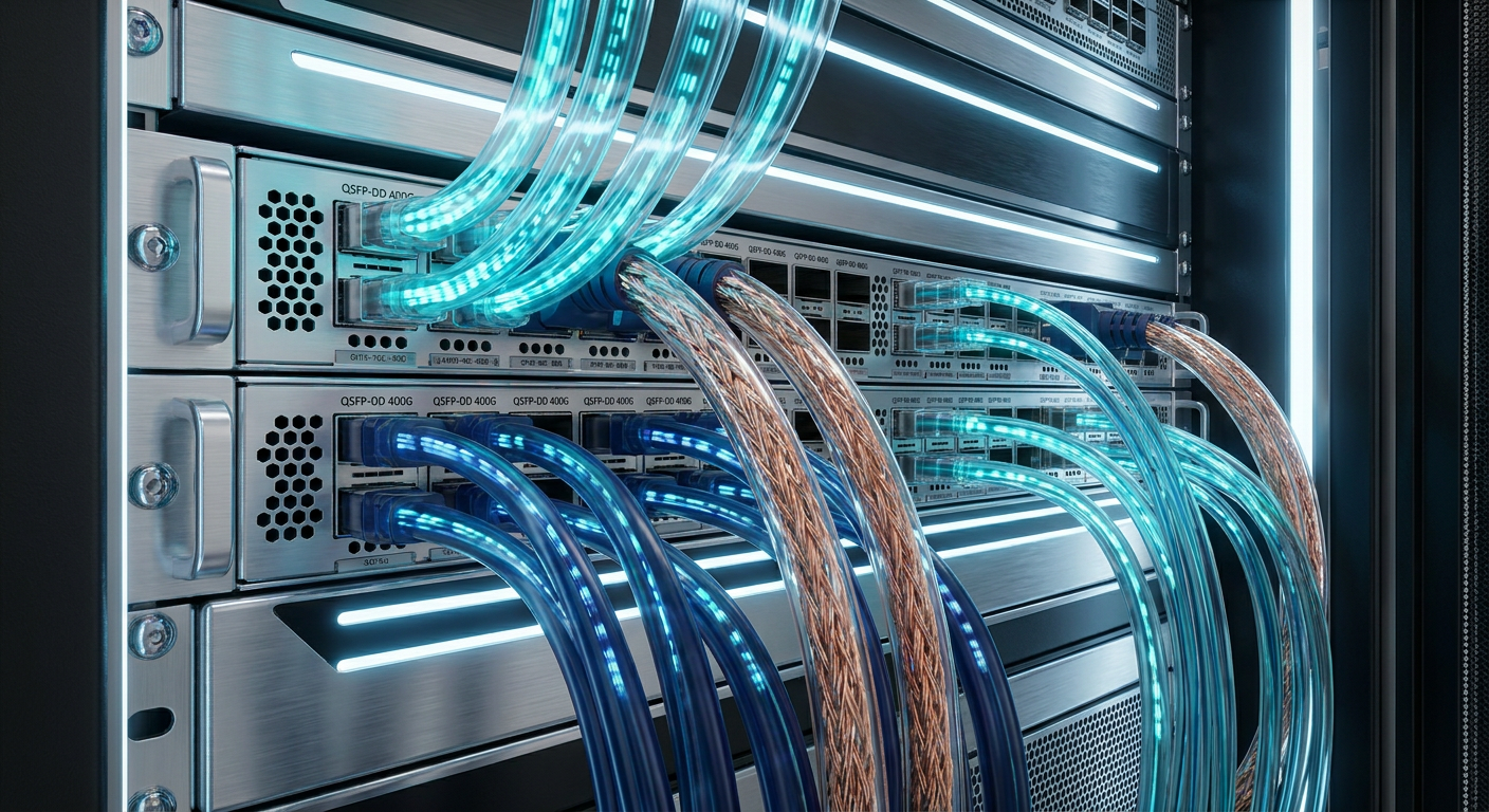
As data center architectures transition from 100G and 200G to 400G, 800G, and emerging 1.6T fabrics, network architects face an unprecedented physical layer challenge. At 112G PAM4 per-lane signaling speeds, high-frequency signal attenuation in electrical conductors increases dramatically. Traditional passive copper cables that once comfortably reached 5 to 7 meters at lower data rates now encounter severe physical limits, often failing to maintain signal integrity beyond 1 to 3 meters.
Selecting the right high-speed interconnect requires balancing physical reach, power consumption budgets, thermal management, cable bulk, and total cost of ownership (TCO). Today's network decision-makers must evaluate three primary point-to-point cable technologies-Direct Attach Copper (DAC), Active Electrical Cables (AEC), and Active Optical Cables (AOC)-alongside high-density Breakout configurations.
This comprehensive guide breaks down the physical mechanisms, electrical performance parameters, and architectural deployment scenarios for QSFP-DD interconnects, providing actionable decision support for high-density enterprise and telecommunication networks.
Technical Overview & Comparison Matrix
To evaluate interconnect media for 400G and 800G QSFP-DD deployments, engineers must analyze several critical parameters defined by the IEEE 802.3ck 112G PAM4 specifications and QSFP-DD Multi-Source Agreement (MSA) standards. These include maximum reach, power dissipation per cable end, latency overhead, physical wire gauge (AWG) or optical fiber type, and overall cost per port.
The table below summarizes the core technical attributes across passive DAC, active AEC, active AOC, and breakout topologies.
|
Interconnect Type |
Physical Medium |
Max Reach (400G) |
Max Reach (800G) |
Power Consumption (Per End) |
Latency Overhead |
Cable Diameter & Weight |
Relative Cost |
Primary Deployment Scenario |
|---|---|---|---|---|---|---|---|---|
|
Passive DAC |
Twinax Copper (Passive) |
1–3 m |
1–2 m |
Very Low (< 0.1 W to 0.5 W) |
~0 ns (Physical propagation) |
Bulkier (AWG 30/28/26) |
Lowest |
Same-rack Top-of-Rack (ToR) to Server |
|
Active AEC |
Twinax Copper + DSP/Retimers |
3–7 m |
3–5 m |
Low-Medium (1.0 W to 2.5 W) |
~100–300 ps (Retimer latency) |
Slimmer (AWG 32/34, 70% space reduction) |
Moderate |
Adjacent-rack / Inter-rack ToR & Switch |
|
Active AOC |
Multimode Fiber (OM3/OM4) + Optics |
1–100 m |
30–100 m |
Higher (2.0 W to 12 W) |
~100–500 ns (E-O/O-E conversion) |
Ultra-light & highly flexible |
Highest |
Cross-rack, Row-to-Row, Core switches |
|
Breakout Assembly |
DAC, AEC, or AOC Fan-Out Media |
Media Dependent |
Media Dependent |
Depends on Endpoint Speeds |
Media Dependent |
Multi-leg Branch Assemblies |
Medium |
800G to 2×400G / 400G to 4×100G Fan-Out |
Key Takeaway: At 112G PAM4 signaling rates, passive copper (DAC) is restricted to short same-rack runs under 2 meters. Active Electrical Cables (AEC) bridge the gap between 3 and 7 meters with active signal retiming and reduced cable diameter, while Active Optical Cables (AOC) remain essential for cross-rack links up to 100 meters.
Direct Attach Copper (DAC) Cables: Low-Power In-Rack Connectivity
Direct Attach Copper (DAC) assemblies represent the simplest and most cost-effective interconnect technology for short-distance high-speed links. A passive DAC consists of a shielded twinax copper cable directly terminated into fixed QSFP-DD connector housings at both ends, containing no active electronic chips or optical components in the data path.
Physical Mechanism and Signaling Constraints
In 400G (8×50G PAM4) and 800G (8×100G PAM4) QSFP-DD interfaces, passive DAC cables transmit high-speed electrical signals directly across copper conductors. However, high-frequency signals suffer from significant insertion loss, skin effect, and dielectric absorption at 28 GHz Nyquist frequencies.
To combat signal attenuation over distance, cable manufacturers must use thicker copper wire gauges:
-
AWG 30: Suitable for short runs up to 1 meter.
-
AWG 28: Extends reach to approximately 1.5 to 2 meters.
-
AWG 26: Required for distances reaching 2.5 to 3 meters, though resulting in a rigid, heavy cable assembly.
Advantages of Passive DAC
-
Near-Zero Power Consumption: Drawing less than 0.1 Watts per end, passive DACs eliminate thermal load from the transceiver housing, conserving electrical power across high-density switch chassis.
-
Lowest Latency: With no signal retiming or optical conversion, latency is dictated purely by the speed of light in copper (~4.5 nanoseconds per meter), making DAC ideal for latency-sensitive High-Performance Computing (HPC) and financial trading fabrics.
-
Lowest Operational & Capital Cost: Free of expensive silicon retimers or laser optics, DAC offers the lowest cost per gigabit of any interconnect media.
Limitations
Passive DAC reach shrinks sharply as data rates increase. While 100G NRZ DACs reached up to 5 or 7 meters, 800G PAM4 passive DACs are practically constrained to 1 to 2 meters. Attempting to run passive DAC over longer distances causes unrecoverable Bit Error Rates (BER) that exceed the host Forward Error Correction (FEC) limit. Additionally, thick AWG 26 twinax bundles create severe cable management clutter and restrict cooling airflow behind dense server racks.
Active Electrical Cables (AEC): The Smart Copper Revolution
Active Electrical Cables (AEC) have emerged as a dominant interconnect technology for 400G and 800G data center fabrics, specifically designed to address the reach and bulk limitations of passive copper without incurring the high cost and power overhead of optical modules.
How AEC Technology Works
Unlike passive DAC, an AEC cable integrates active signal conditioning semiconductor chips-specifically Clock Data Recovery (CDR) and Retimer DSPs-inside the connector module housings at each end.
Host ASIC → Electrical Signal → AEC Retimer (Equalization & Retiming) → Thin Twinax Copper → AEC Retimer → Host ASIC
The retimer chip performs several critical signal processing functions:
-
Continuous Time Linear Equalization (CTLE): Counteracts high-frequency channel loss.
-
Decision Feedback Equalization (DFE): Cleans up inter-symbol interference (ISI) and reflections.
-
Clock and Data Recovery (CDR): Retimes the electrical signal to eliminate accumulated jitter before driving it across the copper twinax conductors.
The AEC Advantage: Extended Reach and Reduced Cable Bulk
By active retiming at both ends, AEC restores the signal eye diagram, enabling high-speed transmission across longer distances while using much thinner wire gauges (AWG 32 or AWG 34 twinax):
-
Extended Reach: Supports stable 3 to 7 meter connections at 400G and 3 to 5 meters at 800G.
-
Up to 70% Outer Diameter Reduction: AWG 32/34 wire significantly reduces overall cable outer diameter (OD) and weight, dramatically improving bend radius and rack airflow.
-
Bit Error Rate (BER) Protection: Built-in retimers maintain pre-FEC BER levels well within the threshold required for IEEE 802.3ck RS-544 KP4 FEC decoding.
Pro Tip: When designing high-density 800G Top-of-Rack switch to adjacent server rack connections, AEC assemblies provide the optimal balance: delivering 5-meter reach with flexible AWG 32 wire while drawing less than 2.5 Watts per end.
Active Optical Cables (AOC): Long-Reach EMI-Immune Cabling
Active Optical Cables (AOC) extend high-speed connectivity far beyond the physical boundaries of copper media. An AOC consists of a multimode fiber (MMF) patch assembly factory-terminated into transceiver housings that integrate Vertical-Cavity Surface-Emitting Lasers (VCSELs), photodiode detectors, and optical driver ICs.
Optical Transmission Architecture
Inside a 400G or 800G QSFP-DD AOC connector, incoming electrical signals from the host switch are passed through a Retimer/DSP, converted into optical pulses by a VCSEL laser array operating at 850 nm, and transmitted over parallel multimode optical fibers (such as OM3 or OM4). At the receiving end, photodiodes convert light back into electrical signals for the destination host ASIC.
Modern high-density data centers rely on advanced optical assemblies and high-density fiber optic and data center connectivity solutions to maintain signal purity across complex network topologies.
Key Advantages of AOC
-
Extended Reach: Supports distances from 1 meter up to 100 meters on OM4 multimode fiber, making it the standard choice for inter-rack, inter-row, and spine-to-leaf interconnects.
-
Complete Immunity to Electromagnetic Interference (EMI): Because transmission occurs via light pulses through dielectric optical glass, AOCs are immune to electrical noise, cross-talk, and ground loop hazards.
-
Ultra-Lightweight & Flexible Routing: Fiber ribbon cables are extremely light and feature tight bend radii, simplifying routing through overhead cable trays and crowded raceways.
Trade-Offs to Consider
-
Higher Power Draw: Optical E-O and O-E conversion engines draw between 2.0 W and 12 W per end, depending on speed and optical generation, increasing overall switch cooling requirements.
-
Cost Premium: Integrated optics and precision optical alignment make AOCs 3 to 6 times more expensive than passive DAC options.
-
Latency Overhead: Optical conversion introduces a small processing latency (~100 to 500 ns per link).
Engineers deploying long optical links frequently integrate precision optical patch cords and jumpers to maintain precise optical alignment and minimal insertion loss across distributed rows.
Breakout Cables: Port Density Optimization & Fan-Out Topologies
In modern enterprise and cloud networks, core switch ASICs often run at higher aggregate speeds than downstream servers or access leaf switches. Breakout cables (also called splitters or fan-out cables) solve this bandwidth mismatch by splitting a single high-speed QSFP-DD host port into multiple lower-speed client ports.
Common QSFP-DD Breakout Configurations
1. 800G QSFP-DD Breakout Topologies
-
800G QSFP-DD to 2× 400G QSFP-DD (or 2× QSFP112): Connects an 800G switch port (8×100G PAM4) to two separate 400G switches or servers (each running 4×100G PAM4).
-
800G QSFP-DD to 4× 200G QSFP56: Splits 800G into four 200G channels (using 50G or 100G PAM4 lanes).
-
800G QSFP-DD to 8× 100G SFP-DD / SFP112: Fans out a single 800G core switch port directly to eight individual 100G server NICs.
2. 400G QSFP-DD Breakout Topologies
-
400G QSFP-DD to 2× 200G QSFP56: Splits 400G (8×50G PAM4) into two 200G links.
-
400G QSFP-DD to 4× 100G QSFP28: Connects a 400G port to four legacy 100G QSFP28 ports (converting PAM4 to NRZ signaling where supported by host silicon/AEC).
Management and CMIS Port Banking
Breakout configurations rely heavily on the Common Management Interface Specification (CMIS 5.0). Through CMIS registers, the host switch configures individual electrical lane banking, power classes, and application modes.
For instance, an 800G port configured for 2×400G breakout instructs the QSFP-DD module to treat electrical lanes 1–4 as Application Channel A and lanes 5–8 as Application Channel B. Forward Error Correction (RS-544 KP4 FEC) must be negotiated independently across each breakout leg to ensure reliable frame alignment.
Custom infrastructure deployments benefit from custom optical pigtails and breakout terminations designed to exact lengths, avoiding excess slack in dense server cabinets.
Architectural Selection Framework: Matching Scenarios to Interconnects
To simplify interconnect selection for 400G and 800G networks, evaluate your physical topology using the scenario-based framework below:
Scenario 1: Same-Rack Server / GPU to Top-of-Rack (ToR) Switch (Distance: < 2 Meters)
-
Recommended Interconnect: Passive DAC
-
Rationale: Minimal distance allows passive copper to maintain low BER. Delivers zero power draw (<0.1W), zero retimer latency, and the lowest possible capital expenditure.
Scenario 2: Adjacent-Rack Interconnects & High-Density Compute Clusters (Distance: 2 to 7 Meters)
-
Recommended Interconnect: Active Electrical Cable (AEC)
-
Rationale: Passive DAC fails signal integrity beyond 2m at 112G PAM4. AEC retimers extend reach to 7m while using thin AWG 32 wire, reducing cable weight and improving rack cooling airflow compared to thick copper twinax.
Scenario 3: Inter-Rack, Cross-Row, or Core Switch Distribution (Distance: 7 to 100 Meters)
-
Recommended Interconnect: Active Optical Cable (AOC)
-
Rationale: Exceeds copper physical limits. AOC offers 100-meter reach over multimode fiber, complete EMI immunity, and ultra-flexible cable management across rack rows.
Scenario 4: High-Density Spine-to-Leaf Port Aggregation
-
Recommended Interconnect: QSFP-DD Breakout Assembly (DAC, AEC, or AOC variant)
-
Rationale: Maximizes switch ASIC utilization by splitting 800G or 400G high-density ports into multiple 400G, 200G, or 100G channels without requiring external patch panels or extra transceivers.
Manufacturing & Quality Standards: The DIMI Engineering Advantage
High-speed interconnects operating at 112G PAM4 per lane leave virtually no margin for optical or mechanical error. Minor manufacturing variations in copper twinax shielding, connector pin planarity, or optical fiber ferrule polish can cause excessive reflection and signal degradation.
As a vertically integrated manufacturer with over two decades of optical and connectivity engineering experience, DIMI manufactures high-reliability optical and cabling products designed to strict industry standards.
DIMI's manufacturing processes include:
-
Certified Quality Management: Operations certified to ISO 9001:2015, ISO 14001, and TL 9000 standards.
-
Rigorous Optical & Mechanical Testing: Every assembly undergoes 3D interferometry, Optical Time-Domain Reflectometry (OTDR), and Bit Error Rate (BER) testing to verify pre-FEC signal margins.
-
OEM/ODM Customization: Tailored cable lengths, custom AWG wire selections, breakout fan-out legs, and specialized outer jacket materials (LSZH, OFNP) to meet regional telecommunication and enterprise specifications.
For more technical whitepapers and manufacturing standards, explore DIMI technical optical engineering insights.
Engineering Summary and Next Steps
Choosing between DAC, AEC, AOC, and Breakout cables is not a one-size-fits-all decision; it requires matching interconnect media to specific rack distances, power budgets, and switch port topologies:
-
Use DAC for the shortest, cost-sensitive same-rack runs under 2 meters.
-
Deploy AEC for 3 to 7 meter adjacent-rack links needing active retiming, reduced cable bulk, and flexible routing.
-
Choose AOC for inter-rack and row-to-row connections requiring up to 100 meters reach and total EMI immunity.
-
Leverage Breakout Cables to optimize switch port density and connect multi-speed network nodes efficiently.
To discuss custom cable lengths, request OEM/ODM technical specifications, or evaluate sample connectivity kits for your 400G/800G rollout, consult the optical engineering team at DIMI.