


In modern power transmission and distribution systems, link fittings make up only 2–5% of total project cost, yet they take on more than 80% of the mechanical load transfer function for the entire line system. According to State Grid statistical data, line failures caused by link fitting quality issues account for 18–22% of total failures. The average economic loss for each major failure reaches RMB 1.5–5.0 million, and it may affect electricity service for tens of thousands of customers. With the large-scale construction of the UHV transmission network, demand for high-end link fittings maintains an average annual growth rate of 12–15%.
What Are Link Fittings?
Fittings used to connect and assemble insulators, suspension clamps, tension clamps, and protective fittings into a suspension string or a tension string are called link fittings, also known as line-hanging parts. In an energized line, link fittings do not perform a conductive function; they only serve a connecting function and bear mechanical loads. They are the "joints" of the transmission line. They connect insulators, suspension clamps, tension clamps, and protective fittings into a complete system.

Link Fitting Model Designations
According to DL/T 683-2010, the model designations of link fittings are shown in the table below.
(Model structure:) Link fitting model designation
Meaning of Each Part of the Link Fitting Model Designation
| 1 | 2 | 3 | 4 | 5 | 6 |
|---|---|---|---|---|---|
| U - U-type Shackle (Plate) | Default: standard type B - UB plate L - extended type |
- | Nominal breaking load (t) | - | - |
| Q - Ball Eye | Default: round-section body P - combined flat + square section body H - extended type, round-section body |
- | Nominal breaking load (t) | - | - |
| W - Socket Clevis Plate | Default: single-plate type S - double-plate type |
J - with grading ring provision (install grading/corona ring) | Nominal breaking load (t) | - | - |
| Y - Extension Link / Extension Rod | H - extension link Z - right-angle extension rod P - parallel extension rod |
- | - | Connection length (cm) | - |
| GD - GD Plate | - | - | Nominal breaking load (t) | - | - |
| V - V-type Plate | - | - | Nominal breaking load (t) | - | - |
| Z - Right-angle Plate (Right-angle Clevis Plate) | Default: double-plate D - single-plate |
- | Nominal breaking load (t) | - | - |
| P - Parallel Plate (Parallel Clevis Plate) | Default: double-plate D - single-plate S - different plate spacing T - adjustable combined parallel plate |
- | Nominal breaking load (t) | Connection length (cm) | - |
| D - Adjusting Plate | B - adjustable-length single plate | - | Nominal breaking load (t) | Min. connection length (cm) | Max. connection length (cm) |
| PQ - Pulling Plate (Stringing Plate) | - | - | Nominal breaking load (t) | - | - |
| L - Yoke Plate (Shape type) | Default: symmetric triangular yoke plate P - asymmetric triangular yoke plate F - square yoke plate |
- | Nominal breaking load (t) | - | Distance between the two farthest bottom holes (cm) |
| L - Yoke Plate (Suspension type) | X - suspension yoke plate, for center-rotating suspension clamp or drooping suspension clamp K - suspension yoke plate, for top-mounted suspension clamp |
Default: for Type I suspension string V - for V-string suspension |
Nominal breaking load (for V-string: nominal breaking load per leg, t) | Number of bundled sub-conductors | Bundle spacing (cm) |
Technical Requirements for Link Fittings
The technical requirements for link fittings shall comply with DL/T 759-2009, "Link Fittings," namely:
The general technical conditions for link fittings shall comply with GB/T 2314-2008.
The nominal load, connection type, and dimensions of link fittings shall comply with GB/T 2315-2008.
Link fittings shall withstand the mechanical loads and environmental conditions that may occur during installation, maintenance, and operation.
The connecting parts of link fittings shall have a locking device to ensure they do not loosen or detach during operation. The locking pin shall comply with DL/T 764.2-2001, "Special Fasteners for Power Line Fittings-Closed-End Pins."
The dimensions and tolerances of the ball head connection area of the ball eye and ball eye plate, and the ball socket connection area of the socket clevis plate, shall comply with GB/T 4056-2008, "Ball-and-Socket Connection Dimensions for Insulator String Components."
The coaxiality tolerance of the centerlines of the hanger-ear bolt holes of link fittings shall not exceed 1 mm.
The length of the thread of load-bearing bolts entering the plate shall not be greater than 1/3 of the wall thickness of the load-bearing plate.
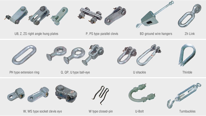
Types of Link Fittings
Classification in DL/T 759-2009
In DL/T 759-2009, link fittings are classified into the following series: ball eye (ball eye plate), socket clevis plate (single-plate, double-plate), U-type shackle, shackle, plate, extension rod, adjusting plate, U-bolt, and yoke plate series.
The shackle series link fittings are divided into extension-ring link fittings and right-angle ring link fittings.
The plate series link fittings are divided into GD-type hanging point fittings, trunnion plate fittings, Z-type plate fittings, ZS-type plate fittings, PD-type plate fittings, P-type plate fittings, UB-type plate fittings, V-type hanging point fittings, and PS-type plate fittings.
The yoke plate series link fittings are divided into L-type yoke plates, square yoke plates, and suspension-type yoke plates.
Classification by Installation Conditions
Link fittings, according to installation conditions, are divided into special link fittings and general link fittings. Special link fittings refer to the ball eye and socket clevis plate that connect to the insulator.
O&M Measures After Installation of Link Fittings
Visual Inspection
| Inspection Item | Normal Condition | Abnormal Condition (Action Needed) | Emergency Defect (Immediate Action) |
|---|---|---|---|
| Galvanized coating | Uniform silvery-white luster | Local yellowing (<10% area) | Red rust (any location) |
| Weld seam | No cracks, full weld bead | Minor crack (<2 mm) | Crack >5 mm or through crack |
| Bolts | No looseness, closed-end pin intact | Closed-end pin slightly deformed | Bolt loosened or pin missing |
| Deformation | No bending | Slight bending (<5 mm) | Obvious bending >10 mm |
Locking Device Inspection
| Status | Description | Corrective Action |
|---|---|---|
| Qualified | Pin legs opened 30–60°, tight against the locked part | Continue use |
| Abnormal | Pin legs opened <30° or >60° | Reinstall during the next maintenance outage |
| Defect | Pin loose, not opened, or missing | Immediately de-energize and correct |
Load Condition Inspection
Connection angle between the link fitting and the insulator: should be vertical, deviation ≤ 5°
Load on both sides of double-plate fittings: should be uniform, with no obvious one-sided loading
Extension rod: no bending deformation
Abnormal signals:
Abnormal color on one side of the fitting (excessive load causes wear of the galvanized coating)
Friction powder at the connection (white or gray)
Plate skewing (possible bolt loosening)
FAQ
Q: What's the practical difference between a suspension string and a tension (dead-end) string from a link fitting standpoint?
A: Suspension strings mainly handle vertical load + swing, while tension strings carry full line tension + angle loads. That means tension strings usually require higher strength margin, tighter alignment control, and stricter locking integrity.
Q: How do I know whether one-sided loading on double-plate fittings is acceptable?
A: It generally isn't. Visible one-sided loading indicates misalignment or incorrect assembly, which increases stress concentration and accelerates wear and deformation. It should be corrected by checking geometry, matching parts, and assembly torque/locking.
Q: If the connection angle is not vertical (deviation >5°), what failures might happen first?
A: Non-vertical alignment increases eccentric loading, which can cause early galvanizing wear, fretting powder, bolt/pin working, and eventually bending deformation or fatigue cracking at high-stress points.
Q: What's the most common installation mistake with locking pins, and why is it risky?
A: Improper pin leg opening (too small/too large), pin not seated tight, or missing pin. These lead to progressive loosening, and once a pin backs out, the connection can fail rapidly under vibration or shock load.
Q: What information should I provide to get an accurate BOM and quote for link fittings?
A: At minimum: line type (conductor/OPGW/ADSS), voltage class, tower type (straight/angle/dead-end), span and climate zone (wind/ice), required strength rating, corrosion environment, and whether you need a full set including protective fittings.
Articles you might be interested in





