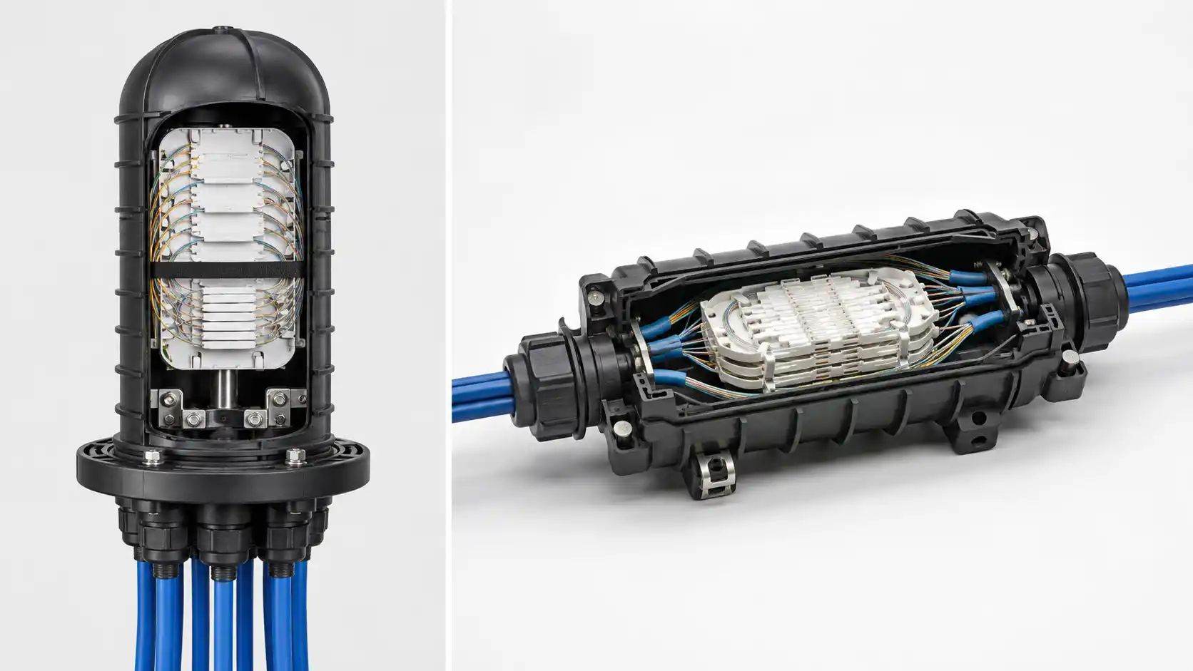
A fiber termination box (also called a fiber terminal box, fiber optic terminal box, or simply FTB) is a compact enclosure used to terminate, splice, connect, protect, and organize fiber optic cables. In FTTH, FTTx, enterprise, and telecom access networks it works as a controlled handover point: incoming feeder or distribution fibers come in on one side, and managed pigtails, patch cords, or subscriber drops go out the other.
For network designers, installers, and procurement buyers, choosing an FTB is not just about box size. The decisions that actually cause field problems are fiber count, splice capacity, adapter and connector type, cable entry design, environmental protection (IP rating and enclosure material), and how easy the box is to open and maintain later. This guide walks through what an FTB does, the common types and specifications, where each one fits, how to choose without buying the wrong unit, and the installation and maintenance details that matter on site.
What Is a Fiber Termination Box?
A fiber termination box is a protective enclosure that manages fiber optic termination points. It gives incoming optical fibers a fixed, routed, and accessible place to be spliced to pigtails and connected through adapters, so that the next part of the network sees clean, repeatable connections instead of bare fiber.
In practical terms, it is the point where a fiber cable enters a building, riser, cabinet, or subscriber area and is converted into manageable links. A typical FTB contains:
- An outer enclosure or shell (indoor plastic, or sealed outdoor housing)
- Cable entry ports and sealing glands
- One or more splice trays
- An adapter plate holding SC, LC, FC, or ST adapters
- Internal fiber routing paths that hold the minimum bend radius
- Cable fixing and strength-member anchoring points
- A slack-storage area for excess fiber
Why a Good Termination Point Matters
Fiber is efficient, but it is unforgiving of poor handling. A weak termination point does not usually fail loudly - it shows up as creeping insertion loss, intermittent links, or a fault that takes hours to trace. A well-designed FTB prevents specific, identifiable problems:
- Macrobend loss is avoided because the routing channels keep fiber above its minimum bend radius instead of letting slack kink behind the splice tray.
- Connector contamination is reduced because mated adapters sit inside a closed enclosure rather than collecting dust on an open panel.
- Tensile stress is not transferred to the splice because the cable jacket and strength member are anchored at the entry, so a pull on the drop cable does not reach the bare fiber.
- Testing and troubleshooting are faster because labeled ports and a clean layout let a technician trace a circuit and connect an OTDR or optical power meter without disturbing neighboring fibers.
-

Main Components of a Fiber Termination Box
Enclosure or Shell
The shell protects the internal fibers and components. Indoor units commonly use ABS or PC plastic; outdoor units use UV-stabilized plastic or metal with proper sealing. Material is not a cosmetic choice - for a pole-mounted or external-wall FTTH access point, UV resistance and a sealed cable entry usually matter more than the box footprint.
Splice Tray
The splice tray holds fusion or mechanical splices and stores fiber slack. It is one of the most decisive internal parts, because splice capacity - not port count - is what often limits a box. A unit can have plenty of adapter ports yet run out of tray space for the splices those ports require.
Adapter Plate
The adapter plate carries the fiber adapters that the outgoing pigtails or patch cords mate into. Common types are SC, LC, FC, and ST, and the polish (UPC or APC) must match the network. If you are unsure which connector family suits your build, this fiber optic connector types guide compares them in detail. The adapters typically pair with a pre-polished fiber pigtail on the splice side.
Cable Fixing and Strain Relief
Cable fixing parts secure the jacket and strength member so pulling force never reaches bare fiber or the splice point. Do not treat this as optional hardware; in MDU risers, where drop cables get tugged during later moves and adds, weak fixation is a leading cause of avoidable splice failures.
Fiber Routing and Slack Storage
Routing channels and a storage area let installers keep enough slack for re-splicing while holding the bend radius. Good routing makes future maintenance possible without re-terminating, and it directly reduces the bend-induced loss described above.
Common Types of Fiber Termination Boxes
Wall-Mount FTB
Fixed to a wall, corridor, building entrance, or riser. Common in FTTH, apartment buildings, and small office networks for low-to-medium fiber counts where access and a compact footprint matter most.
Rack-Mount FTB
Installed in a 19-inch rack or cabinet, usually in telecom rooms, server rooms, and central distribution. It integrates cleanly with patch panels, switches, and OLT/ONT equipment and supports higher density.
Indoor FTB
Built for controlled environments - offices, equipment rooms, residential units, building risers. The design priority is organization, splicing, and patching rather than environmental sealing.
Outdoor FTB
Built for external walls, poles, and outdoor access points. For these, sealing design and cable entry protection are usually more important than enclosure size. Confirm the IP rating, gland sealing, UV resistance, and mounting method before ordering.
Loaded vs Unloaded
A loaded (pre-terminated) FTB ships with adapters, pigtails, or even a splitter installed, which speeds repeated FTTH deployments and improves consistency. An unloaded box gives you the freedom to choose specific adapters, pigtails, or a splitter ratio yourself. Match a loaded box carefully to the exact connector type, fiber type, and port count, or the time you save in the field is lost at procurement.

| Type | Where it fits | Typical capacity | Strengths | Watch out for |
|---|---|---|---|---|
| Wall-mount | FTTH, MDU corridors, small offices | 2–24 fibers | Compact, easy access | Limited room to expand |
| Rack-mount | Telecom rooms, data rooms, cabinets | 12–48+ fibers | High density, clean patching | Needs rack space and planning |
| Indoor | Equipment rooms, residential units, risers | Low–medium | Good organization, lower cost | Little environmental sealing |
| Outdoor | External walls, poles, access points | Low–medium | Sealed against dust, water, UV | Heavier, higher cost, IP rating critical |
| Loaded / pre-terminated | Repeated FTTH rollouts | Fixed by design | Fast install, consistent | Must match connector/fiber/port exactly |
| Unloaded | Custom or mixed deployments | Flexible | Full component flexibility | More field labor and sourcing |
Common Specifications to Check Before Ordering
For a B2B purchase, the datasheet matters more than the product photo. These are the specifications that actually determine whether the box fits your design.
| Specification | Typical options | Why it matters |
|---|---|---|
| Port / fiber count | 2, 4, 8, 12, 24, 48 | Sizes the box to current links plus growth |
| Splice capacity | Trays × splices per tray | Can be lower than port count - verify separately |
| Adapter type | SC, LC duplex, FC, ST | Must match pigtails, patch cords, and equipment |
| Connector polish | UPC, APC (e.g. SC/APC) | APC and UPC must not be mixed on a link |
| IP rating (outdoor) | IP65 / IP66 | Defines dust and water sealing for the site |
| Enclosure material | ABS, PC, UV-resistant plastic, metal | Drives durability and outdoor lifespan |
| Cable entry | Number of ports, gland type | Controls strain relief and sealing |
The IP rating in particular is a precise standard, not a marketing word. Under the IEC's ingress protection (IP) rating system, the first digit grades solid/dust protection (up to 6, dust-tight) and the second grades water protection - so an IP65 outdoor FTB is dust-tight and protected against water jets, which is the usual baseline for external access points.
Fiber Termination Box vs Distribution Box, Splice Closure, and Patch Panel
These four products overlap in some catalogs, and the names are used loosely in different markets. The reliable way to tell them apart is by function and protection level, not by the label.
| Device | Primary function | Typical location | Splicing | Adapter ports | Splitter | Environmental sealing |
|---|---|---|---|---|---|---|
| Termination box (FTB) | Terminate and hand over fibers at an endpoint | Wall, riser, cabinet, access point | Yes | Yes | Sometimes | Indoor or sealed outdoor |
| Distribution box | Distribute fibers to multiple drops | Access / distribution layer | Yes | Yes | Often | Indoor or outdoor |
| Splice closure | Protect splices on a cable route | Aerial, duct, underground | Yes | Rare | Rare | High, sealed for mid-span |
| Patch panel | Organized patching | Rack in telecom room / data center | Sometimes | Yes | No | Indoor |
In short: a fiber distribution box leans toward fanning fibers out to many subscribers (frequently with a splitter), while a fiber splice closure is built for sealed, mid-span splice protection in aerial, duct, or buried routes. A termination box sits between them as the accessible handover and patching point. A patch panel is the right answer when you need high-density rack patching rather than a sealed termination.
Where Fiber Termination Boxes Are Used
FTTH and FTTx Networks
FTBs connect feeder or distribution fibers to drop cables, pigtails, and subscriber equipment. They are a core building block of the access layer; if you are scoping a deployment, this overview of how to build an FTTH network shows where the box fits between the OLT and the subscriber ONT.
Multi-Dwelling Units and Building Risers
In apartment blocks and office towers, FTBs live in risers, corridors, and telecom closets, bridging vertical (riser) and horizontal (floor) cabling. This is where strain relief and clear labeling pay off, because moves and adds happen often.
Enterprise and Campus Networks
Enterprises use FTBs to link buildings, floors, and equipment rooms, keeping inter-building fiber organized and traceable when a fault needs to be isolated quickly.
Telecom Rooms and Equipment Cabinets
Near OLTs, switches, and routers, wall- or rack-mount FTBs create a protected, labeled handover point so live equipment ports are not exposed to ad-hoc patching.
How to Choose the Right Fiber Termination Box
Choosing by lowest price is how teams end up re-ordering. Work through the checklist below before you buy.
| Decision factor | What to confirm | Common mistake to avoid |
|---|---|---|
| Fiber count | Current links plus realistic growth | Buying zero spare capacity |
| Splice capacity | Tray count and splices per tray | Assuming ports equal splice space |
| Indoor vs outdoor | Sealing, gland, IP rating, UV resistance | Using an indoor box outdoors |
| Adapter / connector | Type and polish match end equipment | Mixing APC and UPC on a link |
| Cable entry | Enough entries, correct gland size | Forcing sharp bends at the entry |
| Loaded vs unloaded | Pre-loaded parts match the design | Ordering a loaded box with the wrong ratio |
| Maintenance access | Easy to open, label, and trace | Sealed designs that fight re-entry |
Two points cause more procurement errors than the rest. First, on connector polish: FTTH access typically uses SC/APC because the angled end face lowers back reflection on video and analog overlays, while UPC is common on data links - the two cannot be mated together. If you are deciding between them, this SC/APC guide explains where each belongs. Second, on splitter integration: some FTTH termination and distribution boxes can house a PLC splitter, but only if the box is specified for it - confirm the splitter form factor and the spare tray space before assuming it will fit.
When Not to Use a Fiber Termination Box
An FTB is the wrong tool in a few clear cases:
- Sealed mid-span splicing on a cable route (aerial, duct, or buried) calls for a splice closure built for that level of environmental protection, not a termination box.
- High-density patching in a data center is better served by a fiber patch panel and structured cabling than by stacking termination boxes.
- Pure distribution to many subscribers with splitting usually points to a distribution box sized for that role.
- Harsh outdoor exposure with only an indoor box available - do not deploy it; the lack of sealing will let in dust and moisture.

Installation Steps and Caution Notes
Termination should be done by a trained fiber technician. The exact process depends on the box, but the workflow is consistent.
- 1. Select the location. Choose an accessible, protected spot. Caution: avoid areas exposed to impact, standing water, or routing that forces sharp bends.
- 2. Mount the box. Fix it securely to wall, rack, pole, or cabinet, positioned for later access.
- 3. Prepare the cable. Strip carefully and anchor the jacket and strength member. Caution: never let pulling force reach bare fiber.
- 4. Route fibers inside. Follow the guide channels and keep the minimum bend radius. Store slack neatly, not kinked behind the tray.
- 5. Splice or connect. Fuse incoming fibers to pigtails where required and seat splice protectors in the tray.
- 6. Install adapters and patch cords. Match connector type and polish (UPC/APC) to the design.
- 7. Inspect, clean, and test. Inspect and clean each end face before mating, then verify the link with the right tool - an optical power meter and light source for loss, a VFL to find a break or bad bend, and an OTDR to characterize a longer span.
- 8. Label, close, and re-check seals. Label every port and route, close the enclosure, and on outdoor boxes confirm glands and covers are sealed.
On the inspect-and-clean step, follow a standards-based method rather than cleaning blindly. The IEC defines pass/fail end-face criteria in IEC 61300-3-35, and the FOA's cleaning reference describes the practical inspect, clean if needed, and re-inspect routine.
FAQ
Q: What is a fiber termination box used for?
A: It terminates, splices, connects, protects, and organizes fiber optic cables, creating a safe handover point between incoming fibers and outgoing pigtails, patch cords, or subscriber links.
Q: What is the difference between a fiber termination box and a fiber distribution box?
A: A termination box focuses on terminating, splicing, and protected patching at an endpoint. A distribution box focuses on distributing fibers to multiple drops and frequently houses a splitter. The terms overlap in some markets, so verify the function rather than the name.
Q: What IP rating do I need for an outdoor fiber termination box?
A: IP65 or IP66 is the usual baseline for external access points: dust-tight with protection against water jets. Match the rating to the site - pole and exposed-wall installs need at least this level under the IEC IP system.
Q: How many fibers can a fiber termination box hold?
A: Common sizes are 2, 4, 8, 12, 24, and 48 ports. Small FTTH drops often need only a low-port box, while building distribution and telecom rooms call for 24–48 or more. Always check splice capacity separately from port count.
Q: Can a fiber termination box include a PLC splitter?
A: Some FTTH boxes are specified to house a PLC splitter, but only when the design allows for the splitter form factor and the necessary tray space. Confirm this on the datasheet before assuming it fits.
Q: What is the difference between SC/APC and SC/UPC in FTB applications?
A: APC connectors have an angled end face that lowers back reflection, which is why FTTH access often uses SC/APC, especially with RF video overlays. UPC is common on data links. APC and UPC must never be mated to each other.
Q: What connectors are commonly used in fiber termination boxes?
A: SC, LC, FC, and ST. SC and SC/APC dominate FTTH; LC is common in high-density enterprise and data center environments.
Q: Where should a fiber termination box be installed?
A: In an accessible, protected location suited to cable routing - typically a wall, riser, telecom closet, cabinet, or sealed outdoor access point. Avoid impact zones, water ingress, and any routing that forces sharp bends.
Q: Should I choose a wall-mount or rack-mount fiber termination box?
A: Wall-mount for corridors, building entrances, residential units, and compact installs; rack-mount for telecom rooms, cabinets, data rooms, and higher-density patching.
Conclusion
A fiber termination box is a small component with an outsized effect on network reliability: it protects connections, organizes splices and adapters, and creates a clean, traceable handover point. The buying decision comes down to a few concrete specifications - fiber and port count, splice capacity, adapter type and polish, IP rating and enclosure material, cable entry, and maintenance access - plus knowing when a distribution box, splice closure, or patch panel is the better fit. Map your fiber count, location, connector type, and required protection level first, then choose a box that serves both today's links and your planned expansion.