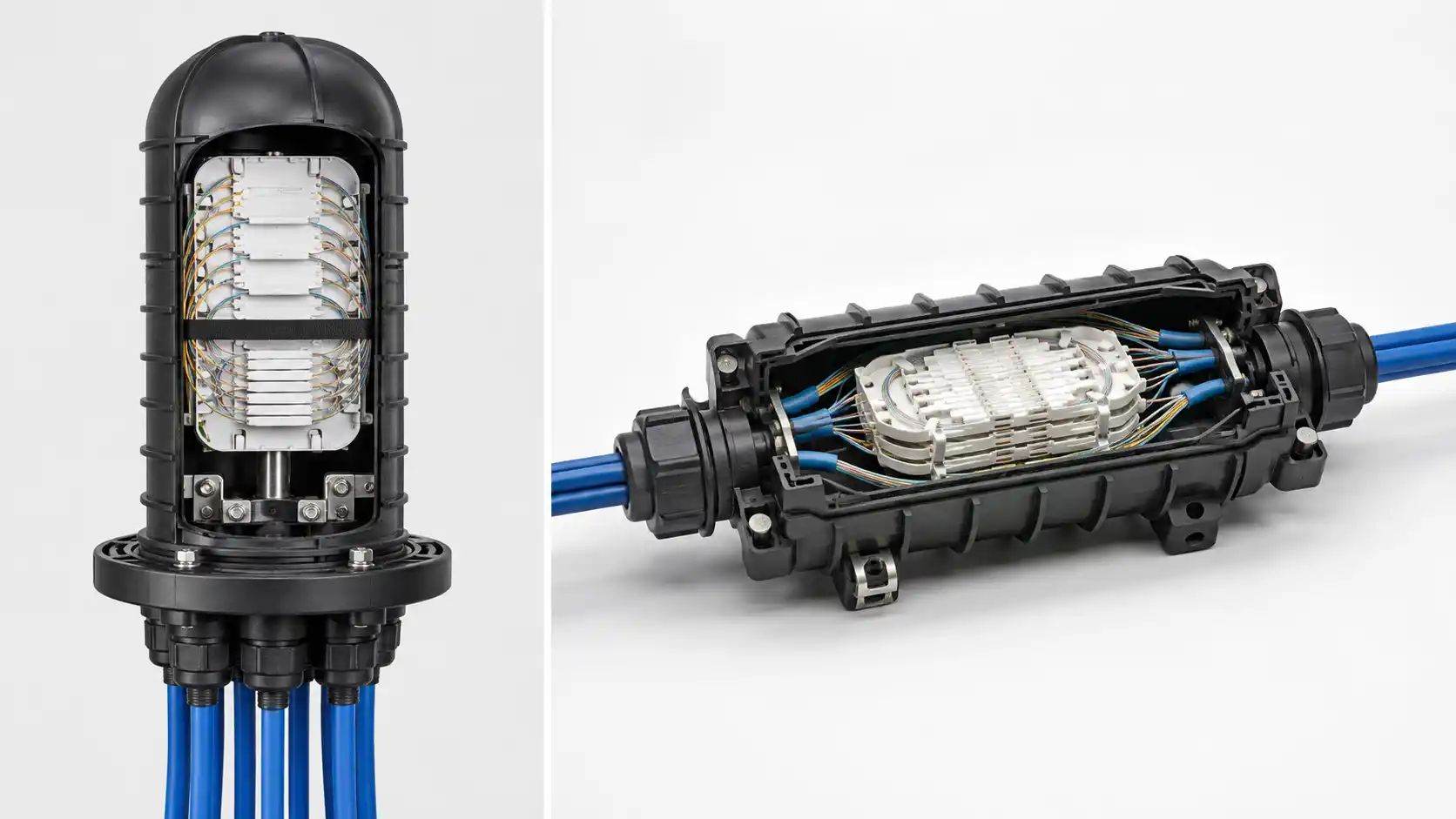
A fiber termination box is the connection and protection point where feeder, distribution, and subscriber drop cables meet inside an FTTH, FTTB, telecom room, or outdoor distribution network. Correct installation determines optical performance, splice protection, cable management, and how easy the box will be to maintain after handover.

This fiber termination box installation guide is written for FTTH contractors, ISPs, distributors, and project buyers who need a practical reference covering selection, installation, acceptance testing, troubleshooting, and B2B procurement. It also covers how to install a fiber termination box for wall-mounted, pole-mounted, and rack-mounted scenarios, including configuration with PLC splitters.
Reviewed by the DIMIFIBER engineering team based on FTTH project configuration practice. For product-level selection, see our companion fiber termination box buying guide.
What Is a Fiber Termination Box?
A fiber termination box is an enclosure that terminates incoming fiber cables, hosts splice trays, fixes pigtails or PLC splitters, and presents adapter ports for patching or subscriber drop connection. Inside a typical FTTH layout, it sits between the feeder cable from the OLT side and the drop cable going to each subscriber's ONU.

The core functions are:
- Protecting fibers from dust, moisture, bending, and mechanical pulling force
- Organizing fiber routing inside a defined path with controlled bend radius
- Providing fiber optic adapter slots for patching and subscriber connection
- Supporting fusion splicing or mechanical splicing with a managed splice tray
- Hosting pigtails and, if required, a pre-installed PLC splitter
- Allowing labeled, traceable port management for later maintenance
For the difference between a termination box, distribution box, and outdoor splice closure, see our overview of the fiber optic box product family.
Where Is a Fiber Termination Box Used in FTTH Projects?

Indoor FTTH and MDU access
In apartment buildings, offices, and multi-dwelling units, the box is normally placed in the weak-current shaft, riser room, corridor distribution point, or floor junction box. It serves several subscribers on the same floor or building section. Compact size, neat fiber routing, and clear port labeling are more important than weather protection here.
Outdoor wall-mounted FTTH drop point
For residential houses, small shops, and low-density access networks, an outdoor fiber termination box is mounted on an exterior wall, eaves, or façade. The box must use sealed cable entries, a UV-resistant housing, and a cover that stays tight after repeated opening for adds and moves. See our outdoor FTTH solution page for typical configurations.
Pole-mounted drop distribution
In suburban, rural, and aerial FTTH networks, the box is mounted on a utility pole as the last drop distribution point before the subscriber. Cable fixing, strain relief, and weatherproof entries are critical because the box is exposed to wind load and constant cable movement. Aerial drop cables entering the box should be anchored using a drop wire clamp outside the box so that no pulling force reaches the splice tray.
Telecom room and data center
In telecom rooms, network cabinets, and data centers, rack-mounted termination boxes manage higher port densities in a controlled indoor environment. For larger port counts that need full patching panels and structured labeling, a dedicated optical distribution frame (ODF) is often more suitable than a small termination box.
Main Types of Fiber Termination Boxes
The table below summarizes the practical differences between the most common form factors used in FTTH and access networks.
| Type | Typical port range | Mounting | Best for | Sealing requirement |
|---|---|---|---|---|
| Wall-mounted indoor FTTH box | 2–24 ports | Wall, weak-current cabinet | MDU floor distribution, indoor drop point | Standard housing |
| Outdoor wall/pole-mounted box | 4–24 ports | Exterior wall, pole | House drops, suburban FTTH, façade distribution | IP65 or higher, sealed entries |
| Rack-mounted termination box | 12–96 ports | 19-inch cabinet (1U–4U) | Telecom room, central office, data center | Indoor only |
| DIN-rail termination box | 2–8 ports | Control cabinet DIN rail | Industrial automation, machine networks | Indoor cabinet |
| Small FTTH terminal box | 2/4/6/8/12/16 ports | Wall, pole (compact) | Building entry, house drop, terminal access | Indoor or outdoor variant |
For higher-density splicing in outdoor or buried scenarios, a fiber optic splice closure is usually the right choice instead of a termination box, because it is dedicated to splicing rather than patching.
Indoor vs Outdoor Fiber Termination Box: What Is the Difference?
This is one of the most common selection mistakes on FTTH projects. The two product families look similar but solve different problems.
| Attribute | Indoor termination box | Outdoor termination box |
|---|---|---|
| Housing material | ABS or thin SPCC, typical indoor finish | UV-stabilized ABS/PC or powder-coated steel |
| Protection level | Usually no formal IP rating | IP65 and above |
| Cable entry | Knockout holes, no sealing | Cable glands or rubber grommets, sealed |
| Cover and lock | Snap or screw, no gasket | Gasket seal, lockable or tool-required cover |
| Mounting | Wall, cabinet, panel | Wall, pole, bracket with stainless steel band |
| Temperature range | 0 °C to +50 °C typical | −40 °C to +70 °C typical |
| Maintenance access | Designed for frequent indoor access | Designed for periodic outdoor inspection |
The rule on site is simple: if the box can see rain, direct sunlight, or condensation, it must be an outdoor model. An "outdoor-rated" claim should be backed by a clear IP rating on the datasheet and matching sealed cable entries.
Fiber Termination Box Selection Table by Application
Use the following matrix when matching a box type to a specific FTTH scenario:
| Application | Recommended box type | Typical ports | Splitter inside? | Notes |
|---|---|---|---|---|
| Single house drop | Small wall-mounted FTTH box | 1–2 | No | Often combined with subscriber ONU |
| Apartment floor distribution (MDU) | Indoor wall-mounted box | 4–12 | Optional 1×4 or 1×8 | Reserve 30% spare capacity |
| Building entry / MDU riser | Larger indoor box | 12–24 | Yes, distributed splitting | Pre-installed pigtails recommended |
| Outdoor wall drop point | Outdoor sealed box | 4–8 | Optional | IP65+, sealed cable glands |
| Pole-mounted drop branch | Outdoor box with pole bracket | 4–16 | Optional 1×4/1×8 | Anchor drop cable outside box |
| Telecom room / FTTB riser top | Rack-mounted box or small ODF | 24–96 | Centralized splitter rack | Use structured patching panels |
Port Capacity Guide: 2, 4, 6, 8, 12 or 16 Port?
Port count should be chosen based on current subscribers, planned growth, and the position of the box in the network. From DIMIFIBER project configuration practice, the following defaults work well:
- 2 port – single house, single tenant, or simple drop reservation
- 4 port – small drop point covering one family unit and a future port reserve; the 4 port fiber termination box is a common choice for residential FTTH
- 6 to 8 port – low-density MDU floor, small office, or rural drop branch
- 12 port – mid-density floor distribution; works well with a 1×8 PLC splitter plus spare adapters
- 16 port – building entry point or shared distribution box with growth headroom
- 24 port and above – better handled by a fiber distribution box or rack-mounted ODF
As a practical rule, leave at least 25–30% of the ports unused at handover. A box that is full on day one is the hardest one to maintain twelve months later.
Centralized Splitting vs Distributed Splitting: Where Does the PLC Splitter Go?
Whether the termination box needs an internal PLC splitter depends on the PON architecture, not on the box itself.
| Design | Where the splitter sits | Best for | Implication for the termination box |
|---|---|---|---|
| Centralized splitting | One large splitter at the OLT side or central distribution cabinet | Dense MDU, areas with predictable subscriber count | Termination box only needs adapters and splice trays; smaller enclosure works |
| Distributed splitting | Smaller splitters (1×4, 1×8) placed close to subscribers | Spread-out residential drops, phased rollout, lower fiber count in the feeder | Termination box needs splitter space, additional pigtail routing, and clearer output labeling |
For an architecture overview before committing to either design, see our reference on AON vs PON FTTH architecture and our PLC splitter guide for choosing the right split ratio. The relationship between split ratio and PON budget follows the loss model in the ITU-T G.984.2 GPON physical layer recommendation.
How to Choose the Right Fiber Termination Box?
Before placing an order, confirm the following parameters together with the supplier:
- Port capacity with at least 25–30% spare
- Adapter type and polish: SC/APC is standard for most FTTH PON networks, while SC/UPC, LC, or FC may appear in legacy or enterprise links - our reference on SC/APC fiber optic cable explains the difference
- Protection level: indoor housing or IP65+ outdoor sealed housing
- Cable entry diameter range matched to feeder cable and drop cable
- Splice tray capacity matched to expected splice count plus spare
- PLC splitter compatibility if distributed splitting is used
- Mounting accessories: wall screws, pole bracket, stainless steel band, or DIN clip
- Pre-installed pigtails and adapters to save on-site time
Tools and Materials Needed
Prepare a complete tool set before opening the first box. Missing tools on site is one of the most common causes of poor splicing and dirty connectors.
- Fiber stripper, cleaver, and fusion splicer (or mechanical splice kit)
- Fiber cleaning kit with isopropyl alcohol wipes and click cleaners
- Heat shrink splice protection sleeves matched to splice tray
- Fiber pigtails with the correct connector type and length
- SC, LC, or FC adapters matching the box panel
- PLC splitter (bare, blockless, or cassette type) if required
- Optical power meter, light source, and OTDR
- Mounting screws, cable ties, cable glands, port labels
- Safety glasses, fiber scrap container, anti-static mat
Step-by-Step Fiber Termination Box Installation Process
The exact procedure varies by model, but the underlying logic is consistent across most FTTH termination boxes.
Step 1: Confirm the design drawing and port plan
Before drilling anything, confirm the port-to-subscriber mapping, splitter output assignment, and cable color code with the network design. A box installed without a port plan will need to be re-labeled six months later.
Step 2: Choose and prepare the installation site
Pick a stable, accessible surface that allows the lid to fully open. For outdoor installation, avoid surfaces with direct rain runoff, check pole diameter for the bracket, and confirm working height for the technician.
Step 3: Mount the box securely
Mark the mounting holes against the box base, then fix the box with wall plugs, brackets, or stainless steel banding for pole mounting. A correctly mounted box does not move when an installer pulls a cable gently during routing.
Step 4: Introduce and fix the incoming cable
Route the feeder cable through the cable gland or grommet. Strip the outer jacket inside the box, then anchor the strength member to the internal cable clamp. This step is what protects the splice tray from any external pulling load - never rely on a cable tie alone for a primary cable.
Step 5: Strip, cleave, and splice the fiber
Strip, clean, and cleave the fiber, then perform fusion splicing. Place the protected splice sleeve into the splice tray in the order shown on the tray label. Detailed best practice is covered in our walkthrough on how to splice fiber optic cable in enclosures.
Step 6: Route fibers and maintain bend radius
Route fibers along the molded path. Maintain a minimum bend radius of 30 mm for typical G.657 single-mode fiber inside boxes - tighter loops cause micro-bending loss that is hard to diagnose later. Leave 0.5 to 1 m of slack per fiber for future re-splicing, coiled inside the tray.
Step 7: Install adapters, pigtails, or PLC splitter
Insert adapters into the panel slots, then connect pigtails or splitter outputs. For distributed splitting, keep splitter input on one side and outputs on the other, with each output going to a clearly numbered adapter. Clean every connector with a click cleaner before mating - this single habit removes the majority of installation-time insertion loss problems.
Step 8: Test optical performance
Use a stabilized light source plus optical power meter for end-to-end loss measurement, and an OTDR trace for fault localization. Compare measured loss against the project link budget. For the calculation method, see how to calculate fiber loss and power budget, and for distinguishing connector reflection from splice loss, see insertion loss vs return loss.
Step 9: Close, seal, and label the box
Before closing, confirm that no fiber is being pinched by the cover. Tighten cable glands on outdoor boxes, then label each port with subscriber ID or splitter output number. Take a photo of the inside layout and store it with the project record.
Installation Acceptance Checklist
Use this checklist before the contractor signs off on the box:
- Box is firmly mounted and does not move under normal cable pull
- All feeder and drop cables are anchored to the internal clamp, not the gland alone
- Bend radius ≥ 30 mm throughout the tray and routing path
- All splice sleeves are seated inside the splice tray, none loose
- Every adapter is fully inserted and dust-capped on the unused side
- End-to-end insertion loss measured and recorded for every active port
- Outdoor cable entries fully sealed; cover gasket seated correctly
- Every active port labeled with subscriber ID or splitter output
- Inside-the-box photo and port table saved to the project file
Maintenance Guide
A termination box is a long-life passive product, but it still benefits from scheduled inspection. The recommended cadence below is a project-configuration starting point, not a fixed rule - adjust based on environment and operator policy.
| Inspection item | Indoor box | Outdoor box | What to look for |
|---|---|---|---|
| Housing and cover | Annually | Every 6 months | Cracks, UV damage, water marks, insect entry |
| Cable entry sealing | - | Every 6 months | Cable gland tightness, gasket condition |
| Strain relief and clamp | On service visit | Every 6 months | Cable clamp tightness, no movement at splice tray |
| Connector cleanliness | Before any re-mating | Before any re-mating | Use click cleaner or alcohol + lint-free wipe |
| Optical performance | On fault, on add/move | On fault, on add/move | Power meter and OTDR comparison vs baseline |
| Port labels and records | On every change | On every change | Update labels, project drawing, and DB |
Common Faults and Troubleshooting Table
| Symptom | Probable cause | First action |
|---|---|---|
| High insertion loss on one port only | Dirty connector or poor mating | Click-clean both ends, inspect ferrule, re-mate |
| High loss on all subscribers behind a splitter | Splitter input fiber pinched or contaminated | Open box, inspect splitter input, re-clean and re-mate |
| Loss varies with temperature | Fiber under stress, tight bend, or pressed by lid | Re-route fiber, check bend radius, verify lid clearance |
| Loss increases gradually over weeks | Moisture ingress on outdoor box, oxidized contacts | Inspect seal, gland, and gasket; dry and re-seal |
| Total link failure | Cable damage, broken splice, or pulled connector | OTDR trace from both ends to locate the event |
| Subscriber identification confusion | Missing or incorrect port labels | Rebuild port table from physical inspection |
For a deeper background on the link planning behind these tests, the Fiber Optic Association (FOA) publishes free public references on insertion loss testing methodology.
Common Installation Mistakes to Avoid
From recurring field reports across FTTH installation teams, the same handful of mistakes account for most rework:
-
-
Using an indoor box outdoors
- Without sealed entries and a UV-stable housing, an indoor enclosure will start leaking within one rainy season.
-
-
Pulling the cable by the jacket, not the strength member
- Any pulling force that reaches the splice tray will eventually break the splice.
-
-
Tight loops in the splice tray
- A loop tighter than the fiber's minimum bend radius will not always show up immediately, but creates a marginal link that fails when temperature changes.
-
-
Skipping connector cleaning
- A factory-pigtailed connector is not the same as a clean connector. Always click-clean before mating.
-
-
Overfilling the box
- Beyond about 80% of nominal capacity, fibers get pressed by the cover and maintenance becomes slow.
-
-
No port labels
- Without labels, the next technician will disconnect the wrong customer.
B2B Inquiry Checklist for Buyers, Contractors, and ISPs
When requesting a quote, provide the following parameters in a single message. This shortens the quote cycle from days to hours.
- Number of ports per box and total quantity
- Indoor or outdoor; required IP rating
- Mounting method: wall, pole, rack, DIN-rail
- Cable entry quantity and outer diameter range
- Adapter type and polish: SC/APC, SC/UPC, LC/UPC, etc.
- Pre-installed pigtails: type, length, quantity
- PLC splitter requirement: 1×4, 1×8, 1×16, mini or cassette format
- Splice tray capacity required
- Housing material preference: ABS, PC, or metal
- Project packaging or kitting needed
- Datasheet, drawing, and IP test report
- Sample requirement before bulk order
For sample requests or project-based configuration, contact the DIMIFIBER team through our project inquiry form. Background on full FTTH deployment is also covered in our reference on how to build an FTTH network.
FAQ About Fiber Termination Box Installation
Q: What is the purpose of a fiber termination box?
A: It protects, splices, and distributes optical fibers, providing a managed connection point between feeder cables and subscriber drop cables, optionally hosting a PLC splitter.
Q: Can an indoor fiber termination box be used outdoors?
A: No. Indoor boxes lack sealing, UV stability, and the temperature range required outdoors. Use an outdoor model with an explicit IP65 (or higher) rating.
Q: How do I choose between a 4 port and a 6 port fiber termination box?
A: If you have 4 active subscribers and no expected growth, 4 ports is enough. If you may add 1–2 subscribers within 12 months, choose 6 ports so you carry spare capacity from day one.
Q: Should the PLC splitter sit inside the termination box or in a separate cabinet?
A: In distributed splitting designs with low subscriber density, putting a 1×4 or 1×8 splitter inside the termination box reduces field hardware. In dense MDUs or large districts, a centralized splitter in a separate distribution cabinet is easier to maintain.
Q: Should SC/APC or SC/UPC be used in FTTH networks?
A: SC/APC is the standard choice for PON FTTH because of its lower return loss, which protects analog video and high-bandwidth services. SC/UPC remains common in enterprise and legacy data links.
Q: What IP rating is required for an outdoor fiber termination box?
A: IP65 is the practical minimum for wall- or pole-mounted outdoor FTTH boxes. Buried or flood-exposed installations should use a sealed splice closure rather than a termination box.
Q: How often should a fiber termination box be inspected?
A: Outdoor boxes benefit from a visual and sealing check every six months; indoor boxes need attention mainly on service visits and add-or-move events. Adjust based on environment, dust, and operator policy.
Q: What causes high insertion loss inside a termination box?
A: The most common causes are dirty connectors, marginal splices, fiber bent below the minimum radius, loose adapter mating, and external pulling force on the cable. Clean, inspect, and re-mate before assuming a deeper fault.
Q: How do I label ports correctly?
A: Use a label that identifies the subscriber ID or splitter output, plus a sequence number that matches the project port table. Take a photo of the labeled panel and store it with the project record.
Q: What is the minimum bend radius for fiber inside the box?
A: For typical G.657 bend-insensitive single-mode fiber, 30 mm is a safe internal radius. Older G.652 fiber should be kept above its specified value, typically 30–50 mm depending on the cable type.
Conclusion
A correctly installed fiber termination box is one of the most cost-effective ways to protect the long-term reliability of an FTTH network. Selection comes first - match port count, IP rating, splitter strategy, and adapter type to the actual application before specifying the model. Installation discipline comes second - anchor the cable, control the bend radius, clean every connector, and label every port. Acceptance testing and clear documentation close the loop and make future maintenance fast instead of forensic.
For project-level configuration with pre-installed pigtails, PLC splitters, and project-based packaging, DIMIFIBER supports custom FTTH terminal box specifications. Detailed product options are available on our fiber distribution box category, and our engineering team can confirm port layout, cable entry size, and splitter compatibility before a bulk order is placed.