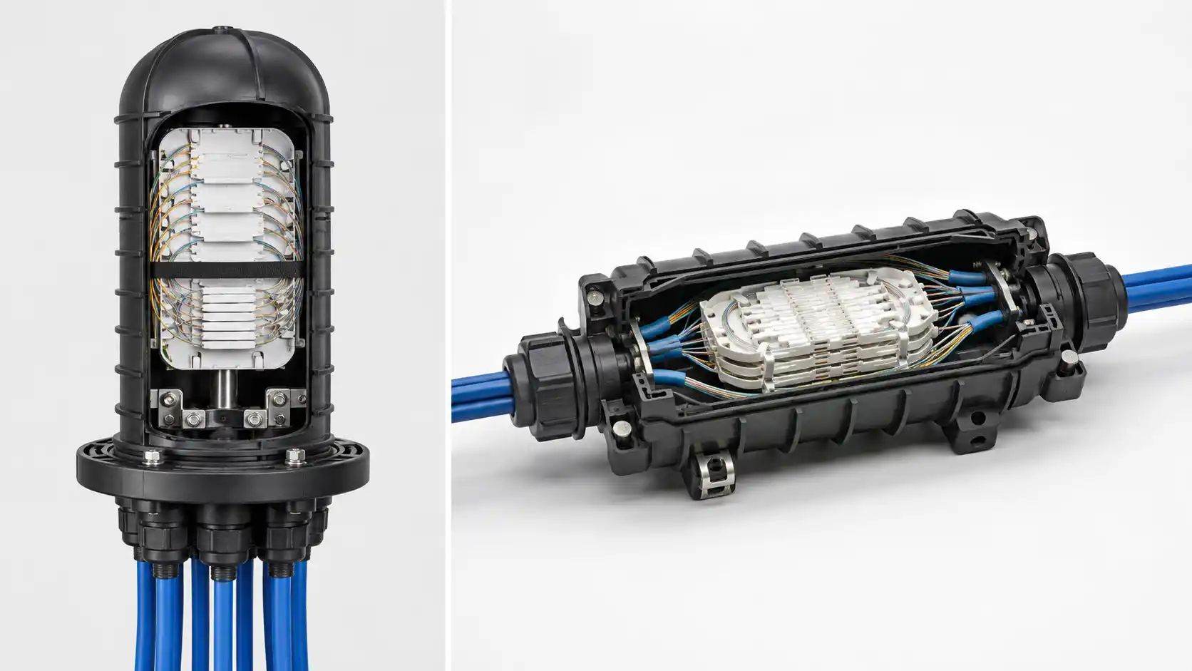
A fiber optic splice closure protects fusion-spliced fiber joints where optical cables are joined, branched, repaired, or accessed in an outside-plant network. It restores environmental and mechanical protection around the opened cable while providing organized space for splice trays, cable restraint, fiber routing, and future maintenance.
The most useful way to select a closure is not to start with a catalog model. Start with the splice plan, installation environment, cable diameters, required splice capacity, port arrangement, sealing method, and expected re-entry frequency. Then compare those requirements with the available closure designs.
Dome and inline closures describe body geometry; capacity describes how many splices the tray system can manage; sealing determines how cable entries and the enclosure are protected; and the installation environment determines which qualification and mounting requirements matter.
What Is a Fiber Optic Splice Closure?
A fiber optic splice closure, also called a fiber splice enclosure, optical splice closure, or fiber joint closure, is installed where a fiber optic cable must be opened and its fibers spliced.
Before the cable is opened, its jacket, strength members, water-blocking materials, armor where present, and other structural layers protect the fibers. At the splice point, some of those layers are removed. The closure provides a protected space around that joint and keeps the internal fibers controlled for installation and future maintenance.
A properly selected closure should support:
- environmental protection against water, dust, contamination, and outdoor exposure;
- mechanical cable restraint so pulling forces are not transferred to the fibers or splice sleeves;
- controlled fiber routing and bend management;
- organized splice-tray storage;
- branching, repair, or mid-span access where required;
- safe re-entry when the network must be expanded or repaired.
The Fiber Optic Association also describes closures used for mid-span access, where a cable is opened while selected fibers or buffer tubes are accessed and other cable elements continue through the location.
Where Fiber Splice Closures Are Used
Fiber splice closures are used wherever an outside-plant cable route requires a protected splice or access point. Common applications include:
- FTTH feeder and distribution networks;
- aerial and pole-mounted fiber routes;
- underground duct systems;
- handholes and manholes;
- campus and industrial fiber links;
- telecom backbone routes;
- repair joints after cable damage;
- mid-span branch locations.
In an FTTH network, the same closure category may be used for a straight-through joint, branch point, or express-access location. Those applications can require very different cable entries, tray layouts, spare capacity, and maintenance access.
Aerial and pole-mounted installations
An aerial closure must be compatible with the intended pole, strand, wall, or messenger mounting arrangement. It also needs adequate cable restraint, suitable outdoor materials, space for cable slack, and a practical re-entry method at the installed position.
Dome closures are common in aerial systems because their cable entries can be concentrated at one end, but an inline closure may also be suitable when the exact model, mounting hardware, and environmental qualification support the application.
Duct, handhole, and manhole installations
Below-grade installations often impose limits on enclosure dimensions, bend space, access, and mounting orientation. Water accumulation may also occur, so both sealing and environmental qualification matter.
A low-profile inline body can be convenient in some handholes, while a dome body may fit better in others. The physical space and cable route should drive the decision rather than a fixed rule based on closure shape.
Direct burial
Direct-burial suitability should be confirmed from the product documentation. The words "outdoor" or "IP68" do not by themselves prove that a closure is qualified for every direct-buried environment.
For route-level installation considerations, see the fiber optic cable installation guide.
Dome vs Inline Fiber Splice Closures
The two most common enclosure geometries are dome and inline. Both protect fiber splices, but they organize cable entries differently.

Dome or vertical closure
A dome closure normally has a base containing the cable-entry ports with a removable dome-shaped housing above it. Cable entries are generally concentrated at one base or end.
This arrangement can be convenient when several cables approach from a similar direction, at branch points, or where a compact vertical body suits the available mounting space.
Inline or horizontal closure
An inline closure generally has an elongated body with cable-entry positions on opposing sides. This can simplify routing when two cable sections approach from opposite directions at a straight-through splice or repair joint.
Dome vs inline comparison
| Selection factor | Dome / vertical | Inline / horizontal |
|---|---|---|
| Cable entry geometry | Usually concentrated at one base or end | Usually arranged on opposing sides |
| Typical route fit | Often convenient for branches and cables approaching from a similar direction | Often convenient for straight-through routes and repairs |
| Mid-span access | Available on models designed for express cable handling | Available on suitable models |
| Capacity | Model-specific | Model-specific |
| Aerial installation | Possible on approved models | Possible on approved models |
| Underground installation | Possible on approved models | Possible on approved models |
| Re-entry | Depends on the sealing system and model | Depends on the sealing system and model |
The important engineering point is that body geometry and installation environment are separate selection factors. A dome closure should not automatically be classified as aerial, and an inline closure should not automatically be classified as underground.
Fiber Splice Closure Capacity: 48, 96, 144 Fibers and Beyond
Closure capacity is usually presented as a fiber or splice count, but the headline number should be treated as the beginning of the selection process rather than the complete specification.
The usable capacity depends on:
- number of splice trays;
- splice positions per tray;
- single-fiber or ribbon splice format;
- space for uncut buffer tubes or expressed cable elements;
- fiber routing between trays;
- spare capacity required for future work.
-

48-fiber closures
A compact 48-fiber closure can fit small distribution points, repair joints, and lower-count FTTH branches when the port layout and tray arrangement match the network.
For example, Dimi Fiber's 48 Fibre Optic Splice Closure is a mini dome design with a maximum 48-fiber capacity using up to four 12-fiber trays. Its standard cable-entry ranges and mechanical sealing system make it a useful example of why capacity, port size, and sealing should be evaluated together.
96-fiber closures
96-fiber closures are common for medium-capacity feeder or distribution joints, but two 96-fiber closures can still differ substantially in body shape, port arrangement, tray structure, and sealing method.
Dimi Fiber's 96 Fibers 1In-2Out Inline Splice Closure uses an inline body and heat-shrink sealing. It illustrates how the same headline capacity can be paired with a different route geometry and maintenance approach than a mechanically sealed dome design.
144-fiber closures
144-fiber capacity is common in feeder, distribution, and backbone applications where more splice positions or branch flexibility are needed.
Dimi Fiber's 144 Fibers 2In-4Out Dome Fiber Optic Splice Closure uses a dome body, mechanical sealing, and a tray system supporting up to 144 fibers. The product page also lists the cable-diameter range and port configuration, which are just as important as the fiber count when matching the closure to a real project.
Do not select to fiber count alone
A 96-fiber cable does not automatically require a product simply because "96 fibers" appears in the closure name. Some fibers may pass through without being spliced, while a branch point may require more splice positions than the feeder's nominal cable count suggests.
Capacity planning should therefore start with the actual splice plan and the operator's expansion policy. Spare capacity can be useful, but there is no universal percentage that fits every network.
Sealing Methods: Mechanical, Gel and Heat Shrink
The sealing system affects installation, cable compatibility, environmental performance, tooling, and re-entry.
| Sealing method | Potential advantage | Main consideration | Typical planning question |
|---|---|---|---|
| Mechanical gasket / O-ring | Can allow repeated opening on suitable designs | Seal surfaces, gaskets, and compression parts must remain correctly installed | Will the closure be reopened regularly? |
| Gel | Can conform around compatible cable entries and simplify field sealing | The cable diameter and gel system must match | Does the approved gel block fit every cable entering the closure? |
| Heat shrink | Can form a robust sealed cable entry when installed correctly | Re-entry may require replacement sleeves or other consumable sealing parts | Is the joint expected to remain closed for long periods? |
These methods should not be ranked as universally better or worse. Performance depends on the complete closure design, correct installation, cable compatibility, and product qualification.

Cable Entry: Port Count and Cable Diameter Range
Port configuration is one of the most important-and most frequently overlooked-splice closure specifications.
A closure can have enough splice capacity and still be unusable because the incoming feeder or outgoing branch cable does not fit an approved entry. For every cable, record:
- outside diameter;
- cable construction;
- entry position;
- whether the cable is cut or expressed;
- required sealing component;
- whether additional branch ports are needed later.
Dimi's current product range shows why this matters. The listed 48F dome model supports specified round and oval cable-entry ranges, the 96F inline model uses a 1-in/2-out arrangement, and the 144F dome model provides a larger branch-oriented port configuration. These are different network tools even though all belong to the same splice-closure category.
Do not assume that a large opening can automatically seal a much smaller cable. The grommet, adapter, gel block, heat-shrink sleeve, or compression seal must be designed for the actual cable diameter.
IP Rating and Environmental Protection
"IP68 fiber optic splice closure" is a common search and procurement phrase. Ingress protection is important, but an IP rating should not be treated as the complete engineering specification of a closure.
IEC 60529 defines degrees of protection provided by enclosures against solid objects and water under stated test conditions. A splice closure must also cope with cable pulling, strain relief, fiber management, temperature changes, impact, re-entry, and the specific installation environment.
For closure-specific qualification, IEC 61753-111-07:2021 addresses sealed closures for Category A, Aerial, while IEC 61753-111-08:2021 addresses sealed closures for Category G, Ground.
North American telecom projects may also reference Telcordia GR-771-CORE, which addresses functional, mechanical, environmental, and performance requirements for fiber optic splice closures.
Instead of asking only, "Is the closure IP68?", ask which standards and tests apply to the exact model, under what conditions it was evaluated, and whether the supplier can provide the relevant technical documentation.
How to Choose the Right Fiber Optic Splice Closure
The selection can be reduced to five practical questions.

1. What happens to the cables at this location?
Define whether the splice is straight-through, branched, mid-span, or a repair. This determines the basic port and routing requirements.
2. How many actual splice positions are required?
Count the expected splices, not only the fibers in the cable. Include branch splices, future work, spare fibers, and the tray configuration.
3. Which cables enter the closure?
Record every cable's outside diameter, construction, armor or strength-member requirements, and whether express access is needed. Then map each cable to an approved port.
4. Where and how will the closure be installed?
Check the physical space, mounting method, environmental qualification, cable bend space, technician access, and applicable project standards.
5. How often will technicians reopen it?
The expected maintenance pattern should influence sealing method, spare-part planning, tray access, and the overall cost of ownership.
Only after these five questions are answered should body style, model, and price be compared.
Fiber Splice Closure vs Fiber Distribution Box
A splice closure primarily protects permanent or semi-permanent cable splices along a fiber route. A fiber distribution box may combine splicing with adapters, splitters, connectorized access, and subscriber distribution.
The practical distinction is the function of the location:
- if the location is mainly a protected cable joint, a splice closure is usually the appropriate category;
- if technicians need connectorized distribution, splitter access, or subscriber-facing ports, a distribution or termination box may be more appropriate.
FAQ
Q: What is a fiber optic splice closure used for?
A: It protects and organizes fiber splices where optical cables are joined, branched, repaired, or accessed along an outside-plant route.
Q: What is the difference between dome and inline splice closures?
A: Dome closures generally concentrate cable entries at one base or end. Inline closures generally provide cable entries on opposing sides. Capacity, sealing, and installation environment depend on the individual model.
Q: Which is better, dome or inline?
A: Neither is universally better. Select the body geometry that best fits the cable approach, port requirements, available space, mounting arrangement, and maintenance plan.
Q: How many fibers can a splice closure hold?
A: Common products cover capacities such as 48, 96, 144, and 288 fibers, but the real limit depends on tray count, splice positions, fiber routing, splice type, and the actual network design.
Q: Can a splice closure be reopened?
A: Many closures are designed for re-entry. The procedure and replacement parts depend on the sealing system and product design.
Q: Can a dome splice closure be installed underground?
A: Yes, when the specific model is designed and qualified for the underground environment. Dome construction alone does not limit a closure to aerial installation.
Q: Is IP68 enough for an underground fiber closure?
A: No. Ingress protection is only one part of the specification. The closure should also be evaluated for its intended environment, cable retention, sealing system, mechanical performance, temperature behavior, re-entry, and applicable project standards.
Q: What information should I send a splice closure supplier?
A: Provide the application, installation environment, splice plan, cable quantity, cable outside diameters, cable constructions, fiber and splice counts, required ports, mid-span requirements, mounting method, re-entry expectations, and required standards or test reports.
Key Takeaway
The right fiber optic splice closure is the one that matches the splice plan, cable architecture, cable-entry sizes, tray capacity, installation environment, sealing method, and maintenance strategy.
Dome versus inline is an important choice, but it is only one decision. Fiber count, port layout, cable outside diameter, qualification, and re-entry can be equally important. Start with the network requirements, then compare suitable models in Dimi Fiber's fiber optic splice closure range.