


What is OTN
OTN (Optical Transport Network) is the next-generation optical transport system standardized by ITU-T, with core standards including G.709 (interface specifications), G.798 (equipment functions), and G.872/873 (network architecture). OTN systems construct a digital layer encapsulation and management framework above the optical layer transmission, realizing an efficient opto-electronic hybrid transport network.
OTN adopts a three-layer nested structure, with each layer responsible for different transport functions:
OPU (Optical Payload Unit) - Optical Payload Unit Layer: Responsible for mapping and adaptation of client signals. It encapsulates different types of client signals (Ethernet, FC, SDH, etc.) into OPU frames through mapping mechanisms (GFP, GMP, BMP). The OPU layer provides an adaptation interface between client signals and the OTN network, supporting flexible bandwidth adjustment.
ODU (Optical Data Unit) - Optical Channel Data Unit Layer: The core transport layer of OTN, providing multiplexing, cross-connection, performance monitoring, and protection switching capabilities. The ODU layer defines multiple rate levels (ODU0/1/2/2e/3/4/flex/Cn), supporting low-speed service multiplexing into high-speed channels. Each ODU frame contains Path Overhead (PM OH) for end-to-end performance monitoring; it supports TCM (Tandem Connection Monitoring) segmented monitoring, allowing up to 6 TCM hierarchy levels to enable independent monitoring across multiple operators or network segments.
OTU (Optical Transport Unit) - Optical Transport Unit Layer: Corresponds to the physical layer interface and includes FEC (Forward Error Correction) functionality. The OTU layer adds Section Overhead (SM OH) and FEC redundancy information on top of ODU, used for optical section-level performance monitoring and error correction. Common FEC schemes include RS(255,239) (7% overhead, approximately 6 dB gain) and SD-FEC/oFEC (10-12 dB gain, suitable for long-distance transmission).

Key Pain Points Addressed by OTN
Multi-rate, Fragmented Services Leading to Wavelength Waste
In metro aggregation, backbone aggregation, data center interconnection, and similar scenarios, multiple service rates such as 1G/10G/25G/100G often coexist. When using only DWDM for wavelength-level transport, fragmented services often struggle to "fill up" a high-speed wavelength, resulting in bandwidth vacancy.
OTN provides sub-wavelength level service encapsulation and multiplexing, enabling low-speed/medium-speed services to be more efficiently aggregated onto high-speed channels, improving wavelength utilization.
Insufficient End-to-End Visibility and O&M Capabilities
DWDM focuses more on optical layer transmission and multiplexing, suitable for "delivering light," but typically lacks the comprehensive end-to-end monitoring, segmented fault location, performance statistics, and accountability capabilities compared to digital layer transport systems at the "service level."
OTN fiber network introduces standardized O&M and performance monitoring mechanisms into the transport structure, providing the transport layer with enhanced alarm, monitoring, fault location, and SLA support capabilities.
Reliability Pressure Under Long-Distance and Complex Optical Layer Conditions
In long-distance, link quality boundary, or complex optical layer design scenarios, error tolerance and stability requirements are higher.
OTN optical transport systems typically combine Forward Error Correction (FEC) and other capabilities to enhance link fault tolerance and transmission performance, increasing reachable distance and stability.
Stricter Service Provisioning and Protection Requirements
When networks require faster service provisioning, clear protection strategies, and stable switching behavior, pure optical layer solutions often need more external support. OTN's transport and O&M mechanisms are better suited to meet "operable, manageable, and guaranteed" transport service requirements.
Core Technologies
Forward Error Correction (FEC) Technology
FEC is a key technology for OTN to improve transmission performance. Through redundant encoding, it enables error detection and correction, enhancing link fault tolerance and transmission distance.
RS(255,239) FEC: The basic FEC scheme defined by G.709 standard, with 7% overhead (16 redundant bytes out of 255 bytes), providing approximately 6 dB coding gain. Suitable for short-to-medium distance transmission (< 80 km) or scenarios with good OSNR.
SD-FEC (Soft-Decision FEC): Enhanced FEC based on soft-decision decoding, with 10-11 dB coding gain and 20%-25% overhead. Suitable for long-distance transmission (80-1000 km) or OSNR-limited scenarios.
oFEC (Ultra-strong FEC): Used for ultra-long-distance submarine cables or extreme conditions, with coding gain exceeding 12 dB and 25%-27% overhead. Typically combined with coherent optical communication technology.
FEC Selection Principles: Short-distance scenarios prioritize low-overhead FEC to improve spectral efficiency; long-distance or OSNR-limited scenarios choose high-gain FEC to ensure link reachability. Comprehensive evaluation should consider OSNR budget, dispersion tolerance, and system margin.
Performance Monitoring and Fault Location
OTN implements network-wide performance monitoring and rapid fault location through overhead bytes:
BIP-8 (Bit Interleaved Parity): Error detection mechanism that calculates parity checks at SM, PM, and TCM layers respectively. The receiving end compares BIP values to count errored blocks (BBE, Background Block Errors).
BER (Bit Error Rate): Calculated based on BIP statistics to evaluate link quality. Typical thresholds: BER < 10^-12 indicates healthy status, 10^-9 ~ 10^-12 indicates degradation, > 10^-9 requires alarm.
Q Factor: A parameter representing optical signal-to-noise ratio, used to evaluate optical layer quality. Q > 15 dB is excellent, 12-15 dB is good, < 12 dB requires optimization.
Delay Monitoring: OTN supports Delay Measurement through PM or TCM overhead for end-to-end or segmented delay statistics, meeting SLA requirements for low-latency services (such as financial trading, industrial control).
TCM Segmented Monitoring: Each TCM level can cover specific network segments or operator domains, independently counting errors, delay, and packet loss for that segment. When end-to-end performance degrades, fault segments can be quickly located through level-by-level TCM, reducing MTTR (Mean Time To Repair).
Protection Switching Mechanisms
OTN provides multiple protection schemes to meet different reliability requirements:
1+1 Linear Protection: Services are simultaneously sent to both working and protection paths, with the receiving end selecting the path with better quality. Switching time < 50 ms (typically < 10 ms), with no service interruption. The drawback is consuming double bandwidth.
1:1 Linear Protection: Under normal conditions, only the working path transmits services, while the protection path is idle or carries low-priority services. In case of failure, switches to the protection path with switching time < 50 ms. Compared to 1+1, it saves bandwidth but requires additional signaling negotiation.
1:N Linear Protection: N working paths share 1 protection path, suitable for scenarios with low failure probability and cost sensitivity. In case of failure, the protection path may be occupied, and switching success rate depends on N value and failure distribution.
SNCP (Subnetwork Connection Protection): Subnetwork connection protection, similar to 1+1 but operating on ring networks. Services are bidirectionally sent on the ring, with the receiving end selecting the high-quality path, switching time < 50 ms. Suitable for metro rings or regional rings.
PP (Path Protection): Path protection, similar to 1:1 but operating on ring networks. Transmits unidirectionally under normal conditions, switches to the reverse path in case of failure. Switching time < 50 ms, with high bandwidth utilization.
Mesh Protection: Dynamic routing and recovery mechanism based on ASON/GMPLS. In case of failure, the control plane calculates backup paths and dynamically establishes connections. Switching time is typically in seconds, suitable for complex topologies and resource optimization scenarios.
What is the Difference Between OTN and DWDM
DWDM (Dense Wavelength Division Multiplexing) is an optical layer multiplexing technology whose core value is carrying multiple wavelength channels on a single fiber to increase fiber capacity. OTN (Optical Transport Network) is a digital layer transport system whose core value is encapsulating, multiplexing, monitoring, and scheduling services. The two are typically used in combination, with OTN transport services carried over DWDM wavelengths.
|
Comparison Dimension |
DWDM |
OTN |
|
Technology Layer |
Optical layer (wavelength level) |
Digital layer (time-slot level) |
|
Transport Granularity |
Wavelength-based (typically >= 10 Gbit/s) |
Supports sub-wavelength multiplexing (minimum 1.25 Gbit/s granularity) |
|
O&M Capabilities |
Optical layer monitoring (OCh, OMS, OTS), primarily power and OSNR |
Service-level monitoring (BER, delay, TCM segmentation), supports end-to-end SLA |
|
Protection Mechanisms |
Optical layer protection (such as OCh SNCP), switching time 10-50 ms |
Digital layer protection (1+1, 1:1, SNCP, PP, Mesh), switching time < 50 ms |
|
Typical Applications |
High-capacity point-to-point transmission, wavelength direct connection, optical layer expansion |
Multi-service aggregation, strong SLA guarantee, complex scheduling and protection |
|
Technical Relationship |
Serves as optical layer foundation, providing wavelength channels |
Overlaid on DWDM, providing service encapsulation and management |
Convergence Architecture: Modern networks typically adopt an OTN over DWDM architecture, where DWDM provides 40/80/96 or even more wavelength capacity, with each wavelength carrying an OTN signal (such as OTU4 100G). The OTN layer is responsible for service mapping, sub-wavelength multiplexing, and end-to-end monitoring, while the DWDM layer handles wavelength transmission and optical layer scheduling (such as wavelength-level routing through ROADM).
Deployment Architecture and Technical Implementation Solutions
Network Topology Selection
Point-to-Point: The simplest topology, suitable for high-capacity transmission between two nodes. Simple deployment, low cost, but lacks protection capability. Applicable scenarios: data center interconnection (DCI), dedicated line services, backbone direct connection.
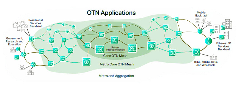
Ring Network: Nodes form a closed loop, supporting bidirectional transmission and ring protection (SNCP, PP). Advantages include fast protection switching (< 50 ms) and high bandwidth utilization; disadvantage is ring capacity limited by the most congested segment. Applicable scenarios: metro aggregation, regional backbone, distributed site interconnection.
Mesh Network: Multiple paths exist between nodes, supporting dynamic routing and load balancing. Based on ASON/GMPLS control plane to implement automatic path calculation, resource reservation, and fault recovery. Advantages include high flexibility and resource utilization; disadvantages include high control complexity and longer switching time (seconds). Applicable scenarios: backbone networks, multi-service scheduling, complex protection requirements.
Common Technical Questions and Answers
What is the difference between ODU2e and ODU2?
ODU2 has a rate of 10.037 Gbit/s, used to carry TDM services such as STM-64; ODU2e has a rate of 10.399 Gbit/s, optimized specifically for 10GE services, reducing mapping overhead. The two are not interchangeable and must be selected based on client signal type.
How to choose between GFP-F and GMP?
GFP-F maintains frame boundaries, suitable for scenarios requiring frame-level processing (such as MAC layer QoS); GMP does not require clock synchronization, suitable for asynchronous scenarios or simplified deployment. For pure transmission requirements, GMP is better; for scenarios requiring OTN layer QoS or traffic policing, choose GFP-F.
Will OTN replace DWDM?
No. DWDM addresses optical layer capacity and wavelength transport, while OTN addresses digital layer encapsulation, aggregation, and O&M management-the two functions are complementary. Modern networks typically adopt a converged OTN over DWDM architecture to integrate optical transport into existing network infrastructure.


