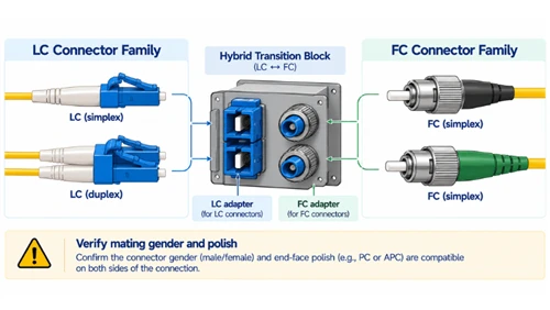
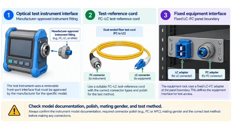
An LC-to-FC fiber adapter can help connect unlike connector interfaces in a mixed fiber network, but it is not automatically the right component for every FC-equipped test instrument. The critical question is where the LC-to-FC transition should live: inside an instrument's approved replaceable interface, in a test-reference or launch cable, or at a fixed legacy panel junction. Choosing the wrong boundary can introduce an avoidable connection, an unsupported instrument modification, or an inaccurate optical-loss measurement.
This guide is for field-test technicians, lab operators, infrastructure maintainers, and brownfield project engineers deciding whether an LC-to-FC fiber adapter for test equipment belongs in the measurement setup or in the permanent cable plant. It focuses on FC test ports and legacy FC panels rather than repeating a general guide to LC, SC, FC and ST migrations. For the broader hybrid-component decision, see DIMI's hybrid adapter vs hybrid patch cord migration guide.
Determine What the FC Interface Actually Is
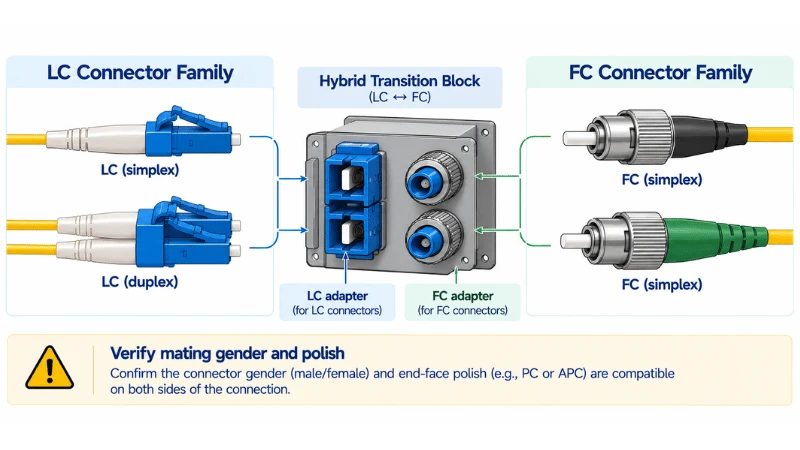
A label reading "FC" can identify several very different boundaries. It might be a threaded FC connector on an instrument's optical source, an interchangeable connector adapter approved by the instrument manufacturer, a bulkhead receptacle on an older patch panel, or an FC plug already attached to a test cord. These parts are not functionally interchangeable simply because they share a connector-family name.
| Observed boundary | First question | Possible correct solution |
|---|---|---|
| Instrument with an approved removable optical interface | Does its manual authorize an LC adapter or a different interface fitting? | Manufacturer-approved interchangeable instrument connector adapter |
| Fixed FC instrument receptacle, LC plant under test | Can a compliant test cord have FC at the instrument end and LC at the link end? | Approved LC-to-FC test-reference or launch cable |
| Permanent FC patch field with LC patching requirement | Should the connector-family transition remain fixed in a panel position? | Correctly specified LC-to-FC hybrid mating adapter or panel redesign |
| Temporary investigation or one-off connection | Can the boundary be contained in a replaceable cable without changing the panel? | Qualified hybrid patch cord, if compatible with the test method |
| Old interface scheduled for removal | Will a fixed hybrid port create a long-term maintenance dependency? | Planned re-termination or connector-panel migration |
The first row is particularly important. VIAVI demonstrates interchangeable optical-power-meter adapters for different connector sizes. Its SmartClass Fiber ORL-85 product documentation likewise identifies interchangeable FC, SC, ST and LC optical adapters. These are examples of model-specific capabilities, not permission to modify every optical test port.
Three Different Components That Are All Called "Adapters"
1. Instrument connector adapter
This is the hardware designed to fit a particular instrument's optical interface. Its replacement method, optical geometry, and suitable connector family are controlled by the tester manufacturer. On some optical power meters, an adapter positions a connector over a detector rather than creating the same connector-to-connector joint used in a cable panel. Never assume that an ordinary LC/FC hybrid coupler can replace such an instrument fitting.
2. LC-to-FC hybrid mating adapter
A hybrid mating adapter creates a fixed, passive junction between two specified connector interfaces. The actual design may have female sockets at both sides for patch-cord plugs, or a different male/female presentation intended for a defined equipment fitting. An LC ferrule and an FC ferrule have different sizes and connector retention arrangements; their compatibility must come from the specific approved hybrid assembly design, not from treating them as interchangeable connector plugs.
It is well suited to a controlled fixed boundary when the legacy panel must remain FC and the exposed patching side is planned as LC. However, the panel must physically accept the adapter, and both physical mating surfaces must satisfy the specified polish and optical requirements.
3. LC-to-FC test-reference or launch cable
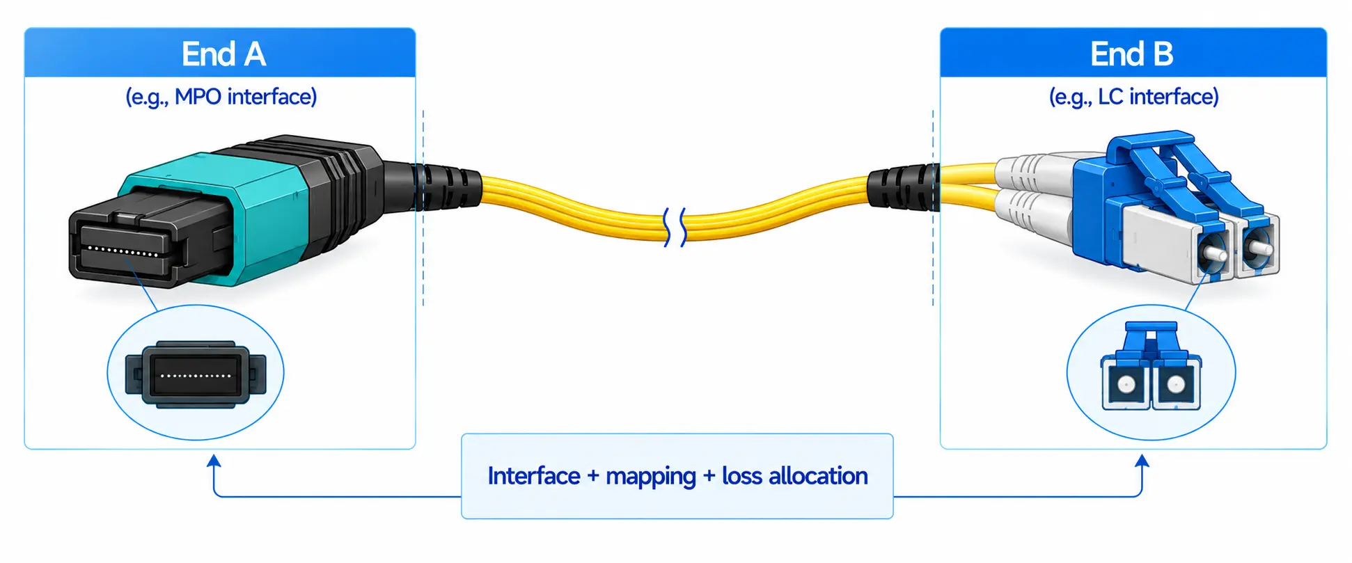
A hybrid test cord has LC on one cable end and FC on the other, without requiring an LC-to-FC mating adapter at a third junction. It may be the correct way to connect an instrument with a fixed FC source port to an LC field link. The connector grade, launch conditions, length, and reference procedure still must be consistent with the instrument instructions and test standard.
Fluke Networks' test-cord guidance explicitly distinguishes test-reference cords, OTDR launch fibers, and port-protection cords and warns that the tester documentation controls whether a cord is suitable. A generic telecom patch cord should not be substituted for a measurement reference cord merely because its plugs fit.
Use a Decision Sequence Specific to FC Test Equipment
Rather than starting with a catalogue search for "LC FC adapter," record the instrument and the legacy link separately.
- Identify the test function. Is the device an optical power meter, light source, optical-loss test set, or OTDR? The measurement setup and connector-reference requirements can differ.
- Record the exact instrument model and port. Capture the model, optical module if applicable, port label, installed interface fitting, and the current manual revision.
- Ask whether the interface is replaceable. If the equipment supports an approved LC fitting, evaluate that first rather than adding a hybrid mating component.
- Define the field connector. Is the plant end LC/UPC, LC/APC, or another known interface? Is the FC end PC/UPC/APC? Record each physical mating point separately.
- Choose the measurement boundary. Keep an instrument-specific change within the instrument's supported accessory system; keep a permanent connector migration in the panel; use an approved test cord when the reference method needs that connection.
- Recheck the reference and acceptance procedure. Determine where the calibrated measurement plane starts and ends, and whether the proposed adapter introduces an additional connection event.
- Release the physical diagram. Show the connector and polish on every side, not just "LC-to-FC" as a line-item description.
When an LC-to-FC Adapter Is the Right Fixed Boundary
A fixed hybrid adapter becomes reasonable when an older FC patch field will remain in service and the facility needs a repeatable LC presentation at a specific bulkhead location. A technician can then troubleshoot and replace the adapter as a documented infrastructure component. The fixed boundary must have an identifiable port number, spare part, permitted connector pairing, and approved loss allocation.
Check the physical implementation before approving the part:
- Side presentation: Does each side accept a male connector plug, or does one side need a male interface to mate to equipment? "LC-to-FC" does not answer this.
- Panel fit: Verify the cutout, mounting clips or flange, anti-rotation feature, threaded access for FC connectors, and clearance behind the panel.
- End-face mating: Record UPC/PC/APC compatibility at each actual optical contact. Do not mate UPC and APC ferrules as a shortcut.
- Optical path: Confirm the installed single-mode or multimode medium and the approved insertion-loss allowance for the complete link.
- Operations: Make sure both sides can be inspected, cleaned, capped, disconnected, and relabeled without disturbing adjacent services.
The DIMI LC-to-FC Fiber Optic Adapters product page is the commercial destination for product-level interface and mounting options. Its publicly stated optical performance and durability figures are product-page claims, not independently verified acceptance criteria for a particular project; request the relevant technical drawing and approved specification before releasing procurement.
When a Hybrid Test Cord Is the Better Boundary
For a mobile tester with a fixed FC connector and an LC-terminated installed link, a properly specified FC-to-LC test cord can be simpler than carrying a separate FC/LC hybrid mating adapter. The instrument end mates with the FC interface it was designed to accept, and the field end presents the approved LC test connector. This also keeps a temporary test setup from becoming a permanent mixed-interface panel.
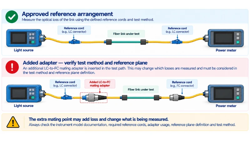
However, test cords are not interchangeable accessories. The appropriate cable depends on whether the measurement is insertion loss, OTDR backscatter, or another optical test; the wavelength and fiber mode; and the reference-grade connector requirements. The Fiber Optic Association's reference-cable guidance explains that reference-cable arrangements and mating adapters determine what loss is included in a measurement. A physical connection that passes light is not proof that the measurement method is valid.
For example, after a one-cord reference is established, inserting an unaccounted hybrid adapter into the launch interface can change the number of measured mated pairs and make the apparent link loss difficult to compare with the approved limit. Use the instrument manufacturer's reference procedure and record any unavoidable transition component.
When to Prefer an Approved Instrument Adapter
Some test equipment can accept different connector families through manufacturer-specified interchangeable port accessories. This may eliminate the need for an external LC/FC hybrid junction altogether. Such an accessory is not interchangeable with a panel-mount coupler, and the change may require a particular tool, procedure, protective cap, or model-specific part number.
Do not assume all instrument ports operate alike. A power-meter detector with interchangeable connector holders, an optical source with a physical-contact launch connector, and an OTDR optical module can impose different conditions. Confirm the type of optical port before selecting an adapter. If the documentation does not explicitly permit the change, treat the fitting as non-interchangeable and consult the instrument manufacturer.
Polish and Fiber Mode: Two Non-Negotiable Checks
Connector family is not polish. FC/UPC-to-LC/UPC can be an appropriate matched-polish pairing when the specific components support it. FC/APC-to-LC/APC is a different configuration requiring the correct mating faces and orientation. A hybrid adapter does not convert an APC optical contact into a UPC contact safely. A hybrid cord may present different polishes at opposite ends because each local mating pair can be matched independently, provided the entire optical application permits those terminations.
Connector family is not fiber mode. An LC/FC fitting does not turn single-mode fiber into multimode fiber. Verify the installed fiber, tester optical module, reference-cord mode, and approved wavelengths. For optical-loss testing, using an unsuitable reference cord or launch condition can invalidate the result even if the connectors are mechanically compatible.
Worked Test Setup: FC Source, LC Legacy Patch Panel
Illustrative scenario, not a reported DIMI installation or validated instrument procedure: A maintenance team is checking an LC/UPC-terminated single-mode route using a light source with a fixed FC/UPC optical output. The far-end meter and the approved test method are defined by the project.
The first choice is not a female-to-female LC/FC adapter. The instrument's FC output may already be a receptacle intended to accept an FC-terminated cord, whereas a female-to-female hybrid coupler expects mating cable connectors at both ends. A hybrid mating adapter also may introduce a connection not anticipated by the reference scheme.
The team should first verify whether an instrument-approved LC port fitting is available. If not, it should evaluate an FC/UPC-to-LC/UPC reference cord that the tester manufacturer and method permit. Only if a genuinely fixed FC-to-LC junction is required should the team evaluate an appropriately gendered hybrid adapter with its own installation and acceptance controls.
| Choice | What it changes | Accept only if |
|---|---|---|
| Approved instrument LC interface | Changes the tester's connector presentation | Manufacturer lists the fitting for this model/port and method. |
| FC/UPC-to-LC/UPC test cord | Changes connector family across a replaceable test cable | Cord grade and reference procedure are approved. |
| LC-to-FC hybrid mating adapter | Adds a defined passive joint between correctly terminated cords | Gender, mating, polish, physical fit and measurement plane are all controlled. |
| Change the legacy field connector | Alters the installed termination | A planned network migration permits new termination and requalification. |
Worked Panel Setup: Retain a Legacy FC Rear Interface
Second illustrative scenario: A legacy equipment rack exposes FC/UPC patching behind a locked service panel, but the maintenance team's new field cords terminate in LC/UPC. The project requires the internal FC-terminated cable plant to remain unchanged during the transition.
Here a qualified panel-mounted LC-to-FC hybrid adapter can be sensible if one side mates with the FC patching and the accessible side accepts the correct LC connector. The acceptance plan must include the mounting cutout, mating style, port numbering, end-face inspection, and installed-channel loss. If the panel has no suitable mount, a controlled hybrid patch cord or a revised termination arrangement may be preferable.
Notice what differs from the test-instrument example: this is a permanent infrastructure interface, not a calibration accessory. The fixed adapter can be part of the as-built panel record, whereas the removable test cord belongs to the measurement kit. Conflating the two creates unclear maintenance ownership.
Inspect and Clean Before Blaming the Connector Conversion
Mixed-interface work involves repeated mating of old FC plugs, new LC plugs, adapter sleeves, and reference cords. A connection that does not seat properly may be a mounting or thread problem; a connection that seats but reads high loss may be dirty, damaged, mis-polished, or measured using the wrong reference method.
- Identify every optical end before removing caps, including the instrument-facing side.
- Use the correct inspection tip and method for the connector and polish; do not assume an LC probe fits an FC ferrule.
- Inspect before mating, clean using an approved process when necessary, and re-inspect.
- Replace physically damaged parts rather than repeatedly tightening a suspect FC connector.
- Keep reference-grade cords segregated from ordinary field patch cords where the test procedure requires that distinction.
- Record which hybrid adapter or cord was present during the final measurement, including its revision or identifier.
Pre-Deployment Checklist for LC-to-FC Test and Panel Transitions
| Acceptance question | Required evidence |
|---|---|
| What exactly is the FC interface? | Instrument manual or as-built panel drawing; port designation. |
| Is an instrument fitting replaceable? | Manufacturer-approved accessory and procedure, not visual resemblance. |
| Where does LC appear? | Field-side mating connector and the approved local polish. |
| Does every component physically mate? | Gender, plug/receptacle arrangement, retaining hardware and fit verified. |
| Is mode and polish compatible? | Single-mode/multimode, UPC/APC and wavelength from authoritative device/link documentation. |
| Will the test method remain valid? | Reference-cord plan, calibration/reference step, and included mating-point count. |
| Can the junction be maintained? | Inspection access, cleaning procedure, replacement strategy and labels. |
| Does the finished route pass? | Project-approved optical result and stored measurement/as-built record. |
Common Problems and First Checks
| Symptom | First check | Do not assume |
|---|---|---|
| Hybrid adapter will not attach to the tester | Instrument port role and adapter male/female presentation | Every FC fitting can accept a female-to-female coupler. |
| LC cable physically connects but loss is unexpectedly high | Cleanliness, connector polish, damage, and the reference method | The adaptor is defective merely because the reading changed. |
| Reference result changes after adding a coupler | Extra mating pair and defined measurement plane | A previous calibration covers any newly inserted connector. |
| Hybrid adapter fits connector but not panel | Mounting profile, thread access, rear clearance and retention | A connector-family match proves panel fit. |
| Instrument requires APC but the field uses UPC | Local polish at each mating interface | A passive mating adapter can safely mate APC directly to UPC. |
Who Owns the Next Decision?
If the open question is the measurement interface, the instrument manufacturer's manual and test method take priority. If the open question is a permanent LC-to-FC panel junction, define the fixed hybrid adapter's two faces, mounting, polish and acceptance, then consult the LC-to-FC adapter product page for commercial configuration. If the network is replacing old FC interfaces entirely, plan a termination migration instead of quietly adding another connector point.
For FC connector type and installed connector-side options rather than hybrid-boundary placement, the DIMI FC/UPC connector product page is a related commercial resource. Avoid selecting a component from its connector name or unverified marketing performance figures alone.
The Engineering Rule
For test equipment, check the instrument-approved connector system and reference procedure first. For legacy panels, define a stable LC-to-FC mating location and maintain it as part of the cable plant. Use an LC-to-FC hybrid adapter only when it is the right physical and operational boundary-not as a generic fix for every mismatched connector label.
FAQ
Q: Can I connect an LC patch cord directly to an FC test instrument with a hybrid adapter?
A: Only if the exact adapter is mechanically compatible with that instrument port and permitted by the instrument's instructions. Some instruments instead support their own interchangeable LC connector fitting, while others are best used with an approved FC-to-LC test cord.
Q: Does an LC-to-FC adapter change a test result?
A: An extra mated interface can contribute loss and may change the measurement plane or reference arrangement. Whether it should be included in the measured link depends on the approved test method. Do not treat connector compatibility as measurement-method approval.
Q: Can an LC/UPC cable be connected to an FC/APC port using one coupler?
A: Not through a direct UPC-to-APC mating pair. A purpose-designed cable or revised termination may be needed so that each local physical connection mates compatible polish types; the optical application must also permit that arrangement.
Q: Is the same solution best for a legacy patch panel?
A: Not necessarily. A fixed LC-to-FC hybrid adapter can make sense at a permanent, accessible and labeled panel interface, while a detachable FC-to-LC cord may be better for a mobile tester. The replacement and acceptance responsibilities differ.