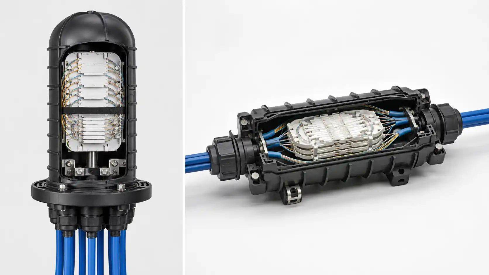
Mixed connector environments are common in brownfield fiber networks. A new switch may use LC while the installed patch panel is SC. Test equipment may use FC while the cable plant is terminated with LC. An older campus segment may still use ST while the replacement electronics use a newer connector family.
The first question is not "Which hybrid adapter should I buy?" It is where should the connector-family transition happen? In practice, the transition can be handled with a hybrid fiber optic adapter, a hybrid patch cord, or a controlled re-termination. Each choice changes the number and location of mating points, the panel hardware, the spare-parts model, the inspection workflow, and the long-term maintenance burden.
This guide focuses on that migration decision. It does not replace a general connector-type guide or the commercial fiber adapter category. If the project is already fixed as an LC-to-SC patch-cord connection, use the LC-to-SC patch cord ordering guide. If the installed plant is specifically ST and the migration endpoint is LC, see the LC-to-ST legacy migration guide.
Start With the Two Interfaces You Actually Have
Before choosing any transition component, document both sides of the connection. "LC to SC" is not enough because connector family is only one compatibility dimension.
| Field | Side A | Side B | Why it matters |
|---|---|---|---|
| Connector family | LC / SC / FC / ST / other | LC / SC / FC / ST / other | Determines the mechanical interface. |
| Polish | UPC / APC / project-defined | UPC / APC / project-defined | The end-face geometry at every physical mating point must be compatible. |
| Fiber mode | Single-mode / multimode | Single-mode / multimode | A transition component does not convert the optical fiber mode. |
| Channel count | Simplex / duplex / other | Simplex / duplex / other | Controls how many optical paths must remain mapped. |
| Interface role | Equipment / panel / cord / test instrument | Equipment / panel / cord / test instrument | Helps decide whether the transition belongs in a bulkhead or in a replaceable cable. |
| Mounting constraint | Existing cutout or receptacle | Required front-side interface | A mechanically correct adapter can still be unusable if it does not fit the panel. |
LC and SC are separate standardized connector families. IEC 61754-20 defines LC connector interfaces, while IEC 61754-4 defines the SC family. A hybrid component exists to bridge different standardized interfaces; it does not make those connector families physically interchangeable by themselves.
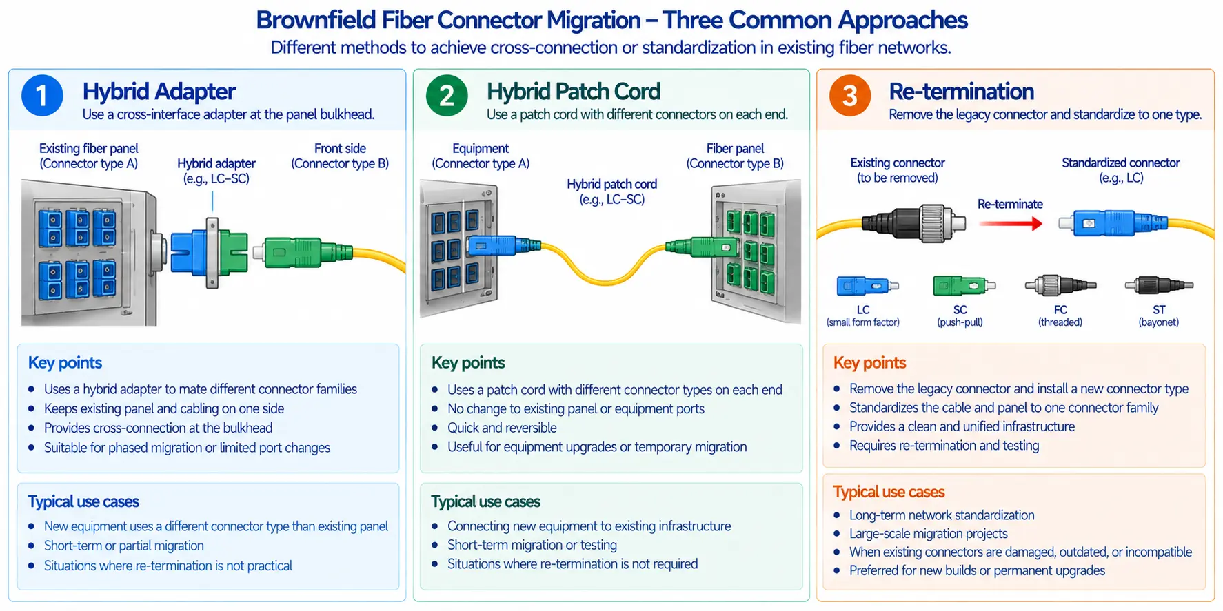
Three Ways to Bridge Different Connector Families
| Method | Best fit | Main advantage | Main control point |
|---|---|---|---|
| Hybrid adapter | Fixed panel or bulkhead where two different connector families must meet at one permanent location | Keeps the transition at a defined infrastructure point | Exact side-A/side-B interfaces, polish compatibility, panel footprint, and adapter condition |
| Hybrid patch cord | Equipment-to-panel or panel-to-equipment connection where each end uses a different connector family | The transition is contained in a replaceable cable assembly | Define both ends independently, including polish, fiber mode, duplex orientation, length, and labels |
| Re-termination or panel migration | Large refresh where one connector family should become the future network standard | Removes a permanent mixed-interface boundary | Outage window, splice/termination method, new panel hardware, testing, and record updates |
None of the three methods is universally best. The right choice depends on how permanent the migration is, how many ports are affected, whether the existing panel can be changed, and which component the operations team should be expected to replace during a fault.
Use a Hybrid Adapter When the Transition Belongs at the Panel
A hybrid adapter is useful when the installed infrastructure should keep one connector family on one side of a bulkhead while exposing another family on the opposite side. Examples include an SC-based cable plant that must present LC toward new equipment, or an FC-terminated test environment that must connect to a different field connector family through a controlled interface.
The important design decision is that the adapter becomes part of the fixed patching infrastructure. That means the panel record, adapter position, connector family on each side, and replacement part must all be controlled.
Use a hybrid adapter when:
- the transition location is permanent and clearly identified;
- the existing cable plant should not be re-terminated;
- the panel or enclosure can accept the required adapter footprint;
- technicians need a stable, labeled migration boundary;
- the approved hybrid adapter supports the exact connector and polish combination on both sides;
- the installed link budget can accommodate the complete mated connection.
A hybrid adapter is less attractive when the panel cutout does not fit the required body, the transition is temporary, the adapter would create an unusual spare part for only one port, or the link also needs to change polish type in a way that would create an incompatible mating pair.
Use a Hybrid Patch Cord When the Transition Should Stay Replaceable
A hybrid patch cord places a different connector on each end of one cable assembly. This is often the cleaner choice when the equipment port and panel port are different but both are already valid interfaces.
For example, an LC/UPC equipment port can connect to an SC/UPC panel using an LC/UPC-to-SC/UPC patch cord. The panel keeps its SC adapter, the equipment keeps its LC receptacle, and the patch cord carries the connector-family transition between them.
This approach is especially useful when:
- the change is at the equipment edge rather than inside the permanent cable plant;
- the transition may be removed during a later equipment refresh;
- the operator prefers standard panel adapters rather than special hybrid bulkheads;
- each end needs a different polish while still mating correctly to its own local port;
- the cable length and routing are already part of the patching workflow;
- replacement by a standard labeled cord is easier than replacing a panel component.
The existing DIMI LC-to-SC patch cord guide shows why both ends must be specified independently. A hybrid cable is not defined only by the two connector names; polish, fiber mode, simplex/duplex construction, polarity, jacket, length, and identification all still matter.
Do Not Use an Adapter as a UPC-to-APC Converter
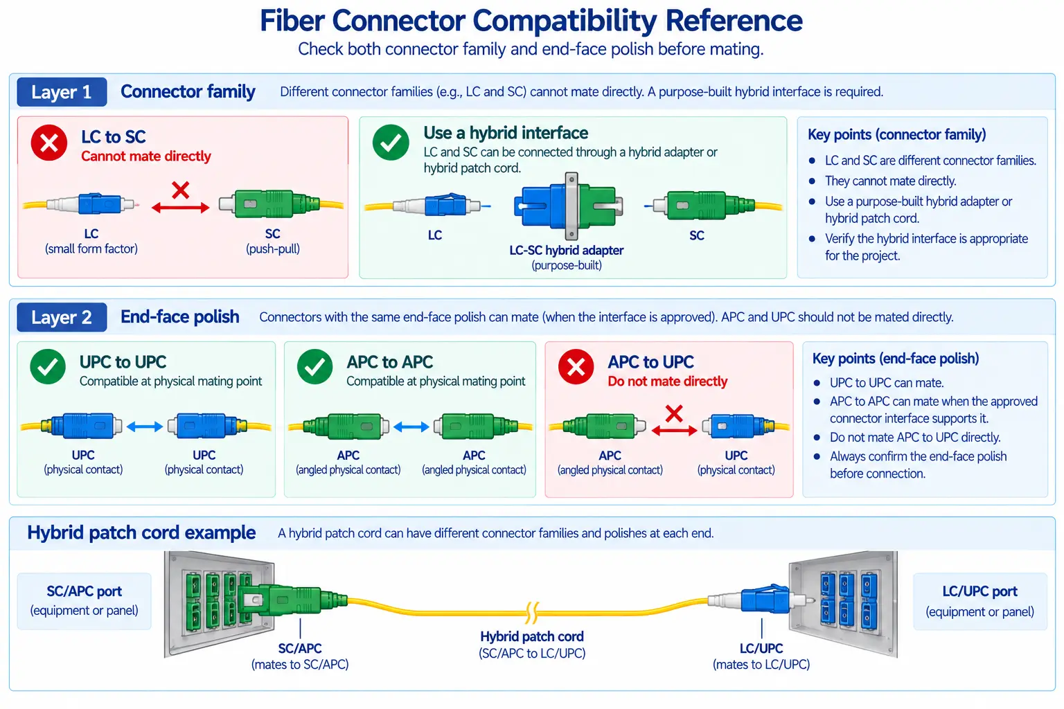
Connector family and polish are separate variables. A component can bridge LC and SC mechanically, but that does not mean it can safely mate a UPC end face directly against an APC end face.
APC ferrules use an angled end-face geometry, while UPC ferrules use a different physical-contact geometry. The Fiber Optic Association specifically advises against using a hybrid mating adapter to connect an SC/APC launch interface directly to an LC/UPC cable plant; its recommended approach is a hybrid cable that presents the correct polish at each local mating point. Fluke Networks also distinguishes APC inspection geometry from UPC and requires the appropriate APC inspection interface when viewing angled end faces.
The practical rule is:
At every physical mating point, define the connector family and polish together.
If one side of a network boundary is SC/APC and the other is LC/UPC, a purpose-built hybrid patch cord can keep SC/APC mating with SC/APC at one end and LC/UPC mating with LC/UPC at the other. Do not assume a female-to-female adapter can "convert" the polish between two incompatible ferrules.
Do Not Expect the Adapter to Convert Fiber Mode
A hybrid adapter changes the mechanical connector interface. It does not convert single-mode optical propagation into multimode propagation or vice versa.
Check the complete link, not only the adapter body:
- fiber type in the installed cable plant;
- fiber type in the patch cord or pigtail;
- transceiver or equipment optical specification;
- connector and adapter construction approved for that link;
- test method and launch conditions appropriate to the fiber mode.
If the two sides of the proposed migration use different fiber modes, the problem is larger than connector conversion. Recheck the active equipment and cable architecture rather than trying to solve the mismatch with a passive adapter.
Duplex Links Still Need a Polarity Plan
A hybrid adapter does not automatically correct transmit/receive polarity. In a duplex link, two optical paths must still arrive at the intended Tx and Rx positions.
Before installation, record:
- which side is equipment Tx and Rx;
- the duplex orientation at Side A;
- the duplex orientation at Side B;
- whether the hybrid adapter or panel holds two independent simplex channels or a defined duplex body;
- the A/B mapping through any hybrid patch cord;
- the final end-to-end Tx-to-Rx relationship.
If a link is dark after a connector-family migration but both optical interfaces are clean and compatible, verify polarity before replacing hardware.
Panel Footprint Can Decide the Architecture
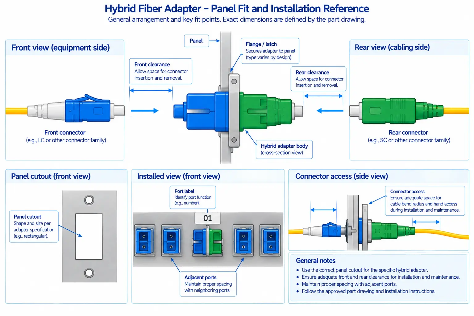
A hybrid adapter can be optically suitable and still fail the installation because its body, flange, latch, or mounting geometry does not match the existing panel.
Check the physical boundary before ordering:
- panel cutout dimensions and retention style;
- front and rear clearance;
- simplex, duplex, or quad position;
- flanged versus flange-less mounting;
- orientation and key access;
- ability to insert and remove both connector types after adjacent ports are populated;
- label visibility and service access.
For retrofit work, review a production-intent sample in the actual panel if the mounting geometry is uncertain. Do not rely on a connector-name match to prove mechanical fit.
Count the Real Mated Pairs in the Link Budget
Hybrid connectivity should be evaluated as part of the full optical channel. Count every actual mated connector pair, splice, passive component, and fiber segment that remains after the migration.
A hybrid adapter at a panel is still a connector mating point. A hybrid patch cord may create two mating points: one at the equipment end and one at the panel or cable-plant end. The correct comparison is therefore the final channel topology, not the number of parts in the shopping cart.
Use project-approved connector-loss values and the actual active-equipment budget. If the link is already close to its limit, measure the migrated path rather than assuming the connector transition is negligible.
Inspection and Cleaning Matter More in Brownfield Migration
Legacy migration work introduces repeated unplugging, inspection, temporary patching, and re-mating. That increases the opportunity for contamination to move between connector end faces and adapter sleeves.
Fluke Networks recommends inspecting connector end faces before mating and notes that adapter sleeves and bulkhead interfaces also need inspection and cleaning control. FOA guidance likewise treats mating adapters as contamination points that can affect repeated connection performance.
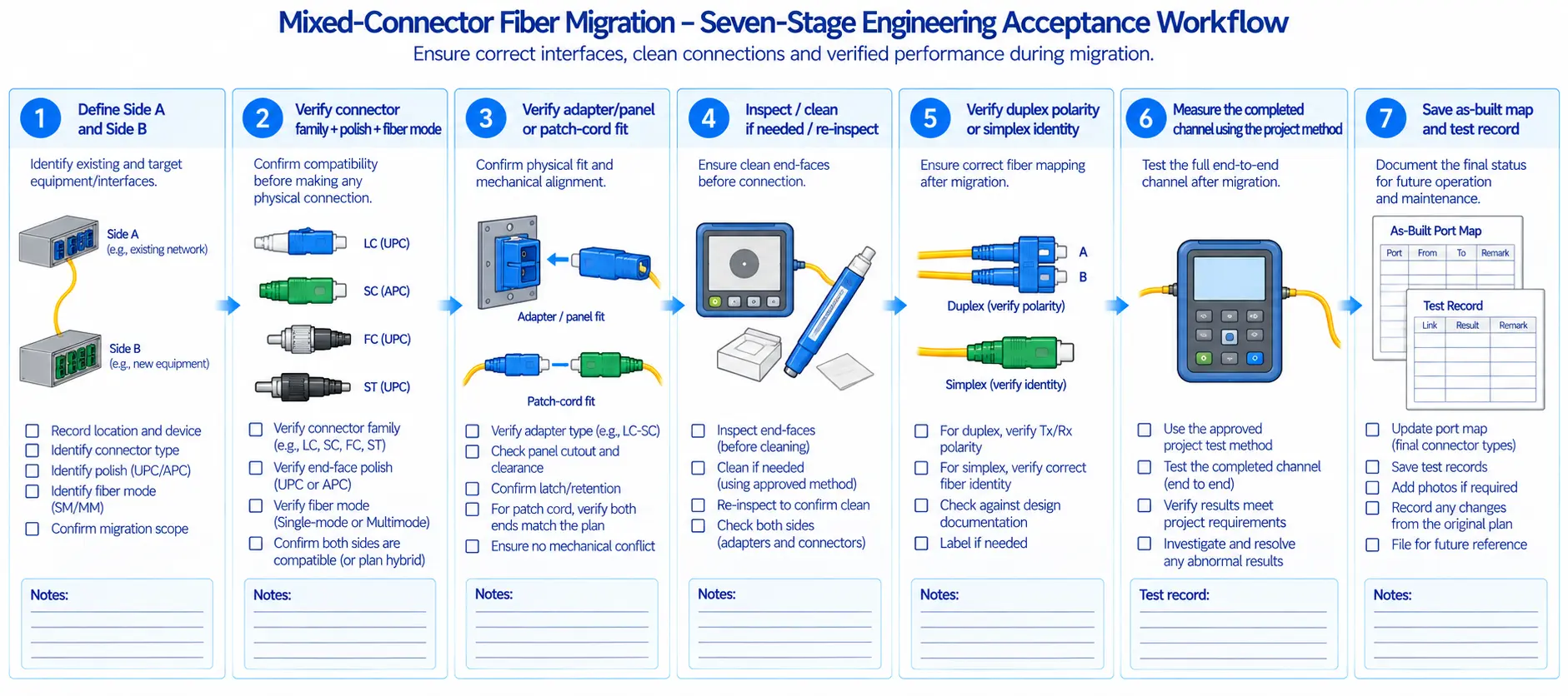
Use a controlled workflow:
- Identify both connector ends before removing caps.
- Inspect each end face with the correct probe or tip for that connector and polish.
- Clean only with an approved fiber-cleaning method when required.
- Re-inspect before mating.
- Protect unused ports and removed cords immediately.
- Record any damaged connector or suspect adapter instead of repeatedly remating it.
Do not assume a new hybrid adapter or factory patch cord is automatically clean. Inspection is the acceptance step; packaging is not.
Acceptance: Prove the Migration Boundary, Then Prove the Channel
A connector-family migration should be accepted in two layers.
1. Migration-boundary acceptance
- verify the connector family and polish on both sides;
- confirm the adapter or patch-cord part matches the approved drawing;
- confirm panel fit and retention;
- inspect and clean all involved end faces;
- verify duplex orientation or simplex identity;
- confirm labels match the network record.
2. Installed-channel acceptance
- perform the project-required insertion-loss test;
- use OTDR or other diagnostics when localization is required;
- compare the completed path with the project optical budget;
- verify the equipment link and relevant diagnostics;
- save the final port map, test result, and migration record.
The migration is not complete merely because the connectors physically mate. The finished link must still meet the same optical and operational acceptance requirements as the rest of the network.
Troubleshooting a Hybrid Connection
| Symptom | Check first | Reason |
|---|---|---|
| Connector will not seat | Connector family, adapter side, keying, and panel orientation | A hybrid component only accepts the interfaces it was designed for. |
| Very high loss immediately after migration | UPC/APC mismatch, contamination, damaged end face, wrong fiber mode | These problems can dominate loss before the adapter itself is blamed. |
| Fault follows the patch cord | Patch-cord connector condition, polarity, and cable construction | The replaceable cable is the common element. |
| Fault stays at the same panel port with known-good cords | Hybrid adapter, sleeve/bulkhead cleanliness, mounting, and connector seating | The fixed port is the common element. |
| Optical power is present but duplex link stays down | Tx/Rx mapping and duplex polarity | Connector-family compatibility does not guarantee correct channel polarity. |
What to Put in a Hybrid Adapter RFQ
When comparing a fiber optic hybrid adapter supplier, specify the migration boundary rather than sending only a phrase such as "LC-SC adapter." Procurement wording should support the engineering definition, not replace it.
- Side A connector family and interface gender;
- Side A polish;
- Side B connector family and interface gender;
- Side B polish;
- single-mode or multimode application;
- simplex, duplex, or other channel arrangement;
- panel footprint, flange/latch style, and orientation;
- housing and sleeve construction if the project specifies them;
- approved insertion-loss and return-loss criteria for the complete mated interface;
- required inspection/test report or sampling plan;
- labeling and color-identification requirements;
- protective caps or shutters if required by the installation;
- drawing revision and change-notification requirement.
For commercial adapter configurations, use the DIMI Fiber Optic Adapter category. Because current website product claims are not automatically verified engineering data, use the approved project datasheet or purchase specification for exact performance limits.
Final Migration Rule
Choose the transition method by deciding where compatibility should be managed for the next maintenance cycle. Use a hybrid adapter when the connector-family boundary belongs in a fixed panel. Use a hybrid patch cord when the transition should remain replaceable at the equipment edge. Re-terminate when the project is ready to eliminate the mixed-interface boundary altogether. In every case, define connector family, polish, fiber mode, channel mapping, panel fit, cleaning, link budget, and acceptance before the migration is approved.
FAQ
Q: What is a hybrid fiber optic adapter?
A: It is a passive interconnection component designed to mate two different fiber connector families at one defined boundary, such as LC on one side and SC on the other. The exact supported interfaces depend on the adapter design.
Q: Can an LC-to-SC adapter connect LC/UPC to SC/APC?
A: Do not assume it can. Connector family and polish are separate compatibility fields. Direct UPC-to-APC mating is not an acceptable polish conversion. Where the two local ports require different polish types, use a transition design that keeps each physical mating pair correctly matched, such as a properly specified hybrid patch cord.
Q: Is a hybrid adapter better than an LC-to-SC patch cord?
A: It depends on where the transition should live. A hybrid adapter fits a fixed panel boundary; a hybrid patch cord keeps the transition in a replaceable cable. Compare panel constraints, port count, spares, cleaning access, and future migration plans.
Q: Does a hybrid adapter add insertion loss?
A: Any mated connector interface contributes to channel loss. Use the approved limit for the complete mated connection and count the actual connection events in the final link budget.
Q: Can a hybrid adapter convert single-mode to multimode?
A: No. It changes connector-interface compatibility, not the propagation mode of the optical link. A single-mode/multimode mismatch must be resolved at the system and cable level.
Q: When is re-termination better than using adapters?
A: Re-termination becomes more attractive when a large migration is intended to standardize the network permanently, special hybrid components would be needed across many ports, or long-term operations would be simpler with one connector family. The outage, splice/termination work, testing, and record changes must still be planned.