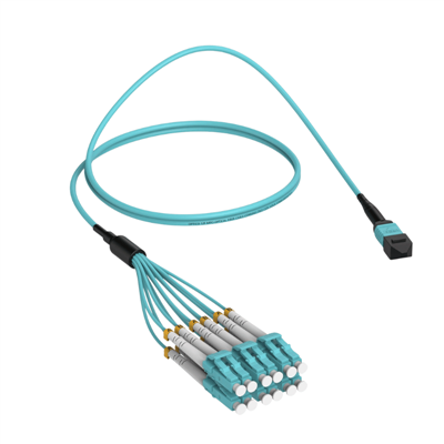
Products Description
| Parameter | Specification |
|---|---|
| Connector A | MPO/MTP Female (12-fiber) |
| Connector B | 6× LC/UPC Duplex |
| Fiber Type | OM5 50/125µm Wideband Multimode |
| Fiber Count | 12 fibers |
| Cable Structure | Round trunk to individual breakout legs |
| Trunk Diameter | 3.0mm nominal |
| Breakout Diameter | 2.0mm per leg (duplex) |
| Jacket Rating | LSZH (OFNP/OFNR optional) |
| Operating Temperature | -20°C to +70°C |
| Storage Temperature | -40°C to +85°C |
| Standard Color | Lime Green (OM5) |
Optical Performance
| Parameter | OM5 Multimode Specification |
|---|---|
| Insertion Loss (MPO) | ≤0.35dB typical, ≤0.5dB max |
| Insertion Loss (LC) | ≤0.3dB typical, ≤0.5dB max |
| Return Loss | ≥20dB (UPC polish) |
| Fiber Attenuation | ≤2.0dB/km @ 850nm, ≤1.5dB/km @ 950nm |
| Bandwidth | ≥3500 MHz·km @ 850nm, ≥1850 MHz·km @ 950nm |
Pre-terminated high-density breakout solution
With OM5 wideband multimode technology, fanning out from single MPO to 6 duplex LC connections, enabling plug-and-play deployment that dramatically reduces installation time and eliminates field termination errors.
Contact Our Team for Polarity Configuration Guidance
Time Savings
Pre-terminated design reduces installation time by up to 70% compared to field termination.
Error Reduction
Factory testing eliminates field termination errors, ensuring reliable performance from day one.

Performance Comparison

OM5 vs OM4 vs OM3
OM5 wideband multimode fiber provides 440m reach for 40GBASE-SR4, compared to 400m for OM4 and 300m for OM3, while supporting additional wavelengths for SWDM applications.
SWDM Support
OM5 fiber supports SWDM-4 technology, enabling 100G transmission over a single duplex OM5 fiber using four wavelengths (850nm, 880nm, 910nm, 940nm).
Future-Proof Design
OM5 fiber is designed to support future higher-speed applications beyond 400G, making it an ideal investment for data centers planning for long-term growth.
Core Features

OM5 Wideband Multimode Technology
Supports Short Wavelength Division Multiplexing (SWDM) transmission with up to 28Gbps per wavelength, providing superior bandwidth density and future-proof capability for 100G/400G applications

Factory Pre-terminated and Tested
Every cable undergoes 100% factory end-face inspection and optical performance testing with typical insertion loss ≤0.35dB, ensuring plug-and-play reliability and consistent performance across all fiber pairs

Flexible Breakout Design
Single MPO/MTP connector fans out to 6 duplex LC connectors with customizable fanout lengths from 0.5m to 1.5m, accommodating diverse rack configurations and cable management requirements
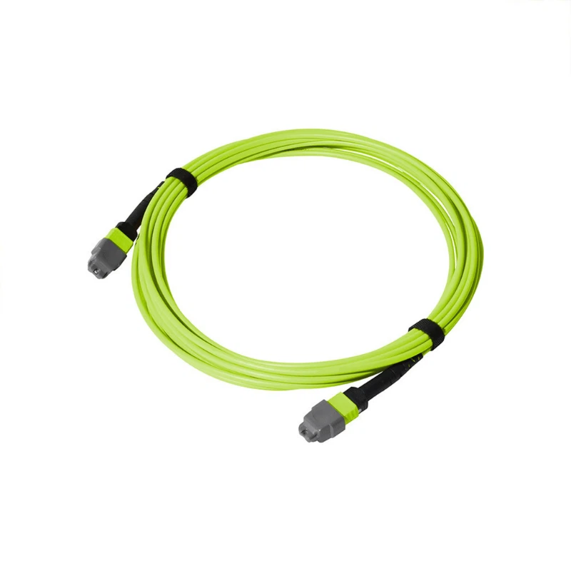
Low Smoke Zero Halogen Jacket
Standard LSZH jacket material complies with data center fire safety standards, with optional OFNP and OFNR ratings available for various building code compliance requirements

Configurable Polarity Options
Available in Type A, Type B, and Type C polarity configurations to support 40GBASE-SR4, 100GBASE-SR4, 100GBASE-SR10, and other parallel optics deployment scenarios

Comprehensive Identification Management
Clear numbering labels on MPO end and each LC connector simplify link tracing, troubleshooting, and documentation, significantly reducing operational complexity in high-density environments
Structure & Polarity Configuration
Cable Structure
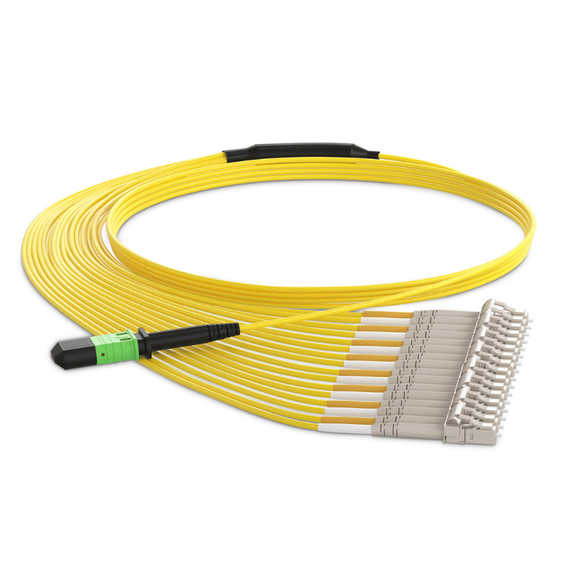
This MPO to LC breakout cable features a rugged round trunk cable (approximately 3.0mm diameter) on the MPO end, transitioning to six individual 2.0mm duplex breakout legs at the LC end. The fanout section is reinforced with a flexible boot and strain relief structure to protect fiber bending radius and ensure long-term mechanical reliability.
Each LC duplex connector is housed in a compact duplex boot with clear fiber position markings (A1/A2, B1/B2, C1/C2, D1/D2, E1/E2, F1/F2) corresponding to the MPO fiber array.
The MPO connector is equipped with alignment pins (male version available upon request) and a push-pull tab mechanism for secure mating in high-density panels. All connectors undergo precision ceramic ferrule polishing and 3D interferometer end-face inspection to ensure optimal physical contact and minimal back reflection.
Polarity Options

Type A Polarity
Straight-through polarity on both ends, commonly used in duplex LC to duplex LC applications when combined with appropriate adapter panels

Type B Polarity
This assembly defaults to Type B polarity, which is the most common configuration for 40G/100G transceiver applications. In Type B, fiber positions are straight-through on one end and flipped on the other end, creating the necessary crossover for proper transmit-to-receive pairing in parallel optics systems.

Type C Polarity
Pair-flipped polarity provides an alternative crossover method for specific equipment configurations requiring different polarity schemes.
Applications

Data Center Spine-Leaf Architecture
Connect 40G/100G spine switches to leaf switches via MPO trunk infrastructure, with breakout to individual server connections at 10G/25G speeds using LC interfaces, enabling scalable and efficient east-west traffic flow.

Structured Cabling Deployment
Link MPO-based cassettes or adapter panels in main distribution areas to LC patch panels in equipment distribution areas, enabling flexible port configuration, simplified moves-adds-changes, and scalable network growth without major infrastructure overhaul.

High-Performance Computing Clusters
Provide high-density interconnection between compute nodes and storage arrays, supporting SWDM transmission for maximized bandwidth utilization in bandwidth-intensive workloads such as artificial intelligence training and scientific simulations.

40G/100G Transceiver Breakout
Enable direct connection from QSFP+/QSFP28 transceiver modules to multiple 10G/25G SFP+/SFP28 ports, facilitating cost-effective network migration strategies and mixed-speed deployments during technology refresh cycles.

Testing and Lab Environments
Offer flexible connectivity for validation testing of parallel optics equipment, polarity verification procedures, and system integration scenarios requiring multiple LC connections from single MPO source for comprehensive network testing.
Network Topology Example

Core Switch (MPO ports) → MPO to LC Breakout Cable → Edge Patch Panel (LC ports) → LC Jumpers → Access Layer Switches/Servers
In a typical data center deployment, 40G or 100G core switches equipped with MPO/MTP interfaces connect to structured cabling systems via this breakout cable. The MPO end plugs directly into the switch port or into an MPO cassette module mounted in the switch-side patch panel, while the six LC duplex connectors fan out to a standard LC patch panel positioned in the equipment distribution area.
From there, individual LC patch cords complete the connection to end devices operating at 10G or 25G speeds. This architecture provides a clean migration path from legacy 10G infrastructure to modern 40G/100G backbone networks while maintaining backward compatibility with existing LC-based equipment.
Standards, Testing & Warranty
Compliance Standards
IEC 61754-7:
International standard for MPO/MTP connector optical and mechanical interface specifications
TIA-568.3-D:
ANSI/TIA standard for optical fiber cabling components and transmission performance requirements
IEC 61300-3-34:
Test procedure for fiber optic connector return loss measurement and characterization
IEC 60332-1:
Fire resistance testing standard for single cable vertical flame propagation behavior
RoHS Directive:
Compliant with EU restrictions on hazardous substances in electronic equipment manufacturing
REACH Regulation:
Meets European chemical safety requirements for materials used in cable construction and connector components
Factory Testing Process
3D Interferometry Inspection
Every connector end-face undergoes automated 3D interferometer inspection to verify critical geometry parameters including radius of curvature, apex offset, fiber height, and surface finish.
Insertion Loss Testing
Each cable assembly is tested on calibrated equipment measuring insertion loss across all fiber pairs using both reference-grade light sources and power meters.
Return Loss Verification
Return loss measurements confirm proper polishing quality and minimal back reflection using optical time-domain reflectometry (OTDR).
Continuity and Polarity Check
Automated polarity testing equipment verifies correct fiber-to-fiber mapping according to specified polarity type (A, B, or C).
Quality Assurance & Warranty
All MPO to LC breakout cables include a comprehensive 3-year manufacturer warranty covering materials and workmanship defects under normal operating conditions.
Extended Warranty Options:
Available for mission-critical deployments requiring additional coverage or performance guarantees.
ISO 9001 Certification:
Our quality management system maintains ISO 9001 certification, ensuring consistent product performance and reliability.
Traceability:
Complete traceability records are maintained for all cable assemblies, enabling rapid root cause analysis if issues arise.
Customization Options
Custom Lengths
Any length from 1 meter to 100 meters available with precise length tolerance of ±0.1m; longer lengths possible for outdoor-rated versions with armored cable construction for campus backbone applications.
Fiber Type Selection
Choose from OM3, OM4, OM5 multimode options, or OS2 singlemode for long-distance campus applications requiring extended reach.
OM5 (Lime Green)Standard
OM4 (Erika Violet)Optional
OM3 (Aqua)Optional
OS2 (Yellow)
Fiber Count Variations
Available in 8-fiber, 12-fiber, 24-fiber, and 48-fiber configurations to match transceiver requirements and port density needs.
8-fiber4 duplex LC
12-fiber6 duplex LC (Standard)
24-fiber12 duplex LC
48-fiber24 duplex LC
Connector Polish Options
Standard UPC polish for multimode applications; APC available for singlemode versions requiring ultra-low back reflection.
UPC Polish
Ultra Physical Contact
Standard
APC Polish
Angled Physical Contact (8°)
Optional
Pin/No-Pin Configuration
MPO connectors available with or without alignment pins; specify male (with pins) or female (no pins) to match existing infrastructure.
Female (No Pins)
MPO connector without alignment pins
Standard
Male (With Pins)
MPO connector with alignment pins
Optional
Jacket Ratings
Choose from LSZH, OFNP, OFNR, or outdoor-rated jacketing with UV resistance and armored protection.
- LSZH (Low Smoke Zero Halogen)Standard
- OFNP (Plenum-rated)Optional
- OFNR (Riser-rated)Optional
- Outdoor-rated (UV resistant)Optional
Related Products & Accessories

MTP/MPO Cassette Modules
Pre-loaded cassette modules with integrated MPO-to-LC or MPO-to-MPO adapter configurations, enabling tool-free installation in standard rack-mount enclosures.

MTP/MPO Patch Panels
High-density patch panels accommodating multiple MPO adapter ports, providing centralized interconnection points for trunk cables in distribution areas.

MPO Connector Cleaning Tools
Specialized cleaning pens and cassettes designed for MPO/MTP multi-fiber connectors, featuring precision cleaning tips that simultaneously clean all fiber end-faces.
Hot Tags: mpo to lc fiber cable-om5-12 fibers, China mpo to lc fiber cable-om5-12 fibers manufacturers, suppliers, factory