Product Overview
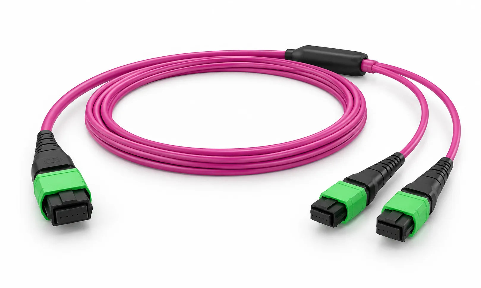
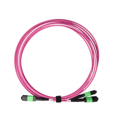
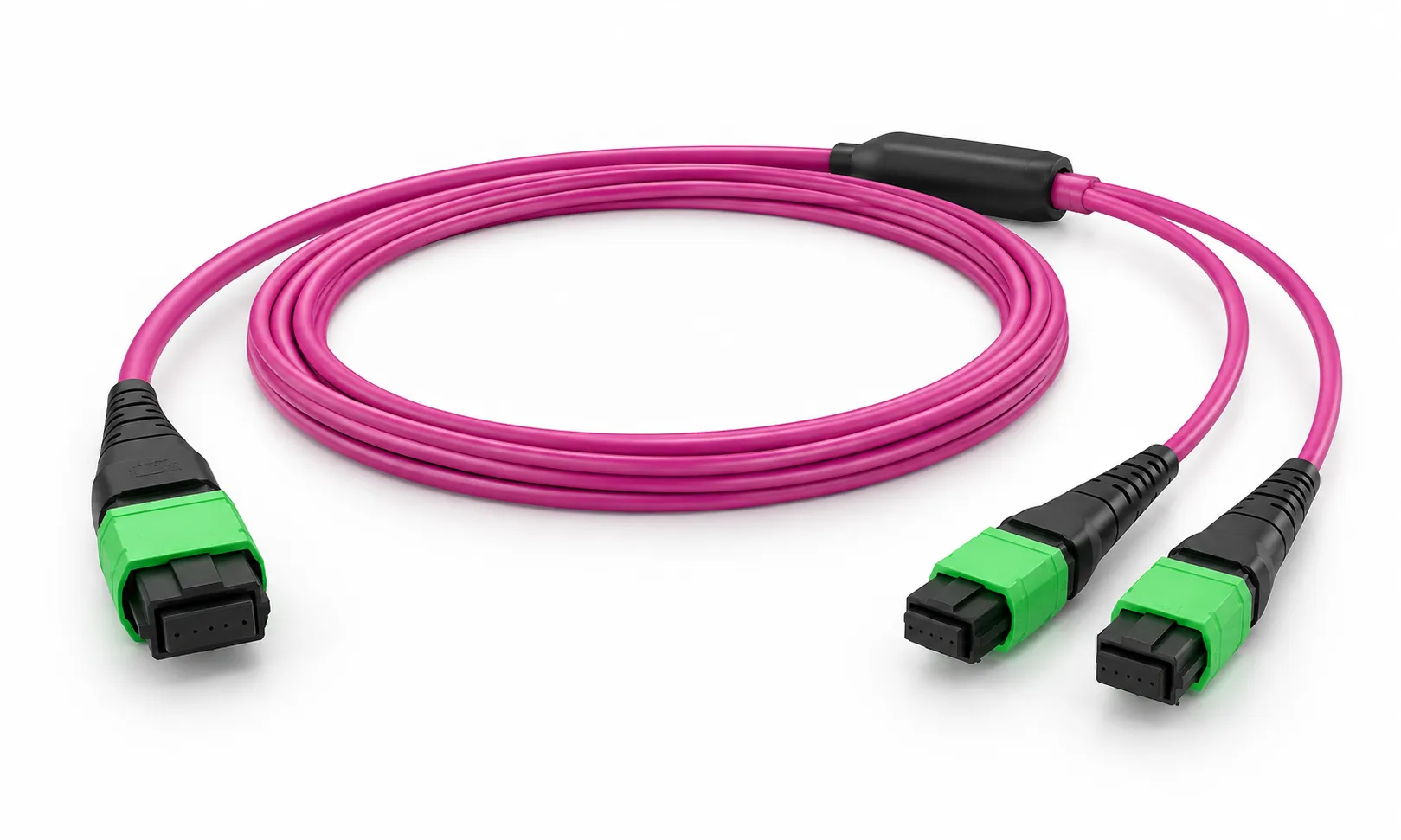
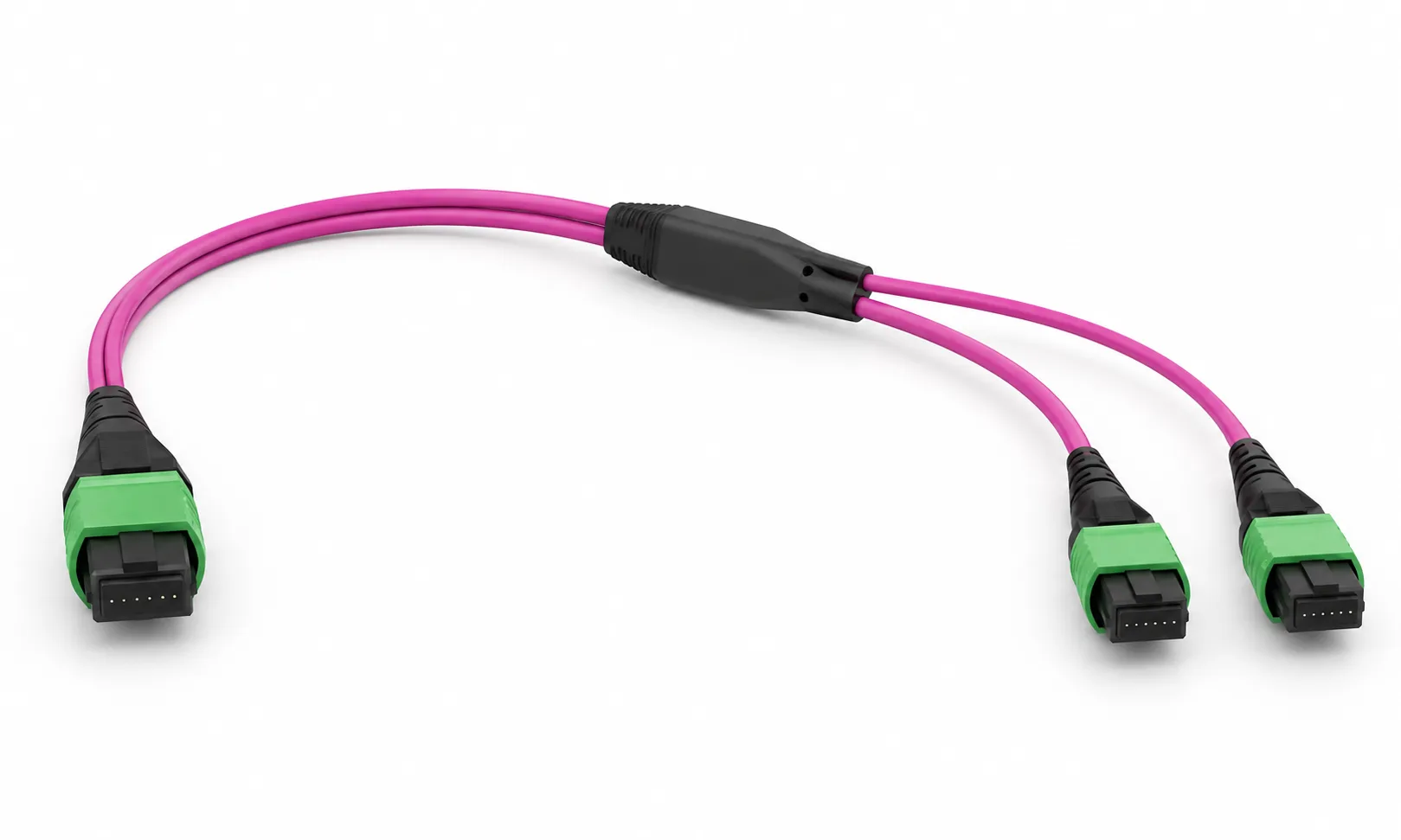
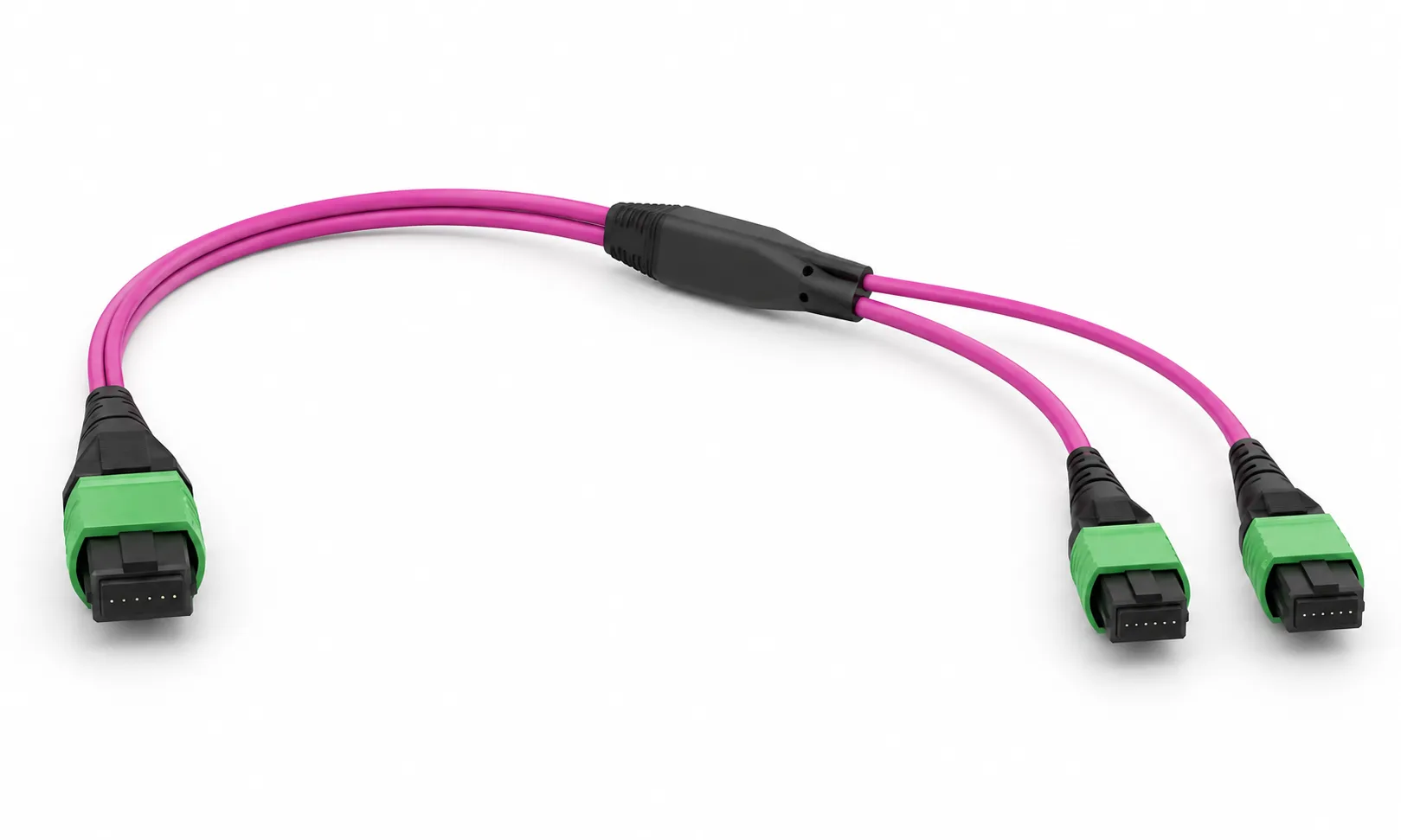
DIMI 16 Fiber MPO-16 APC to 2× MPO-8 APC OM4 Breakout Cable converts one 16-fiber parallel optical interface into two independent 8-fiber MPO connections for high-density data center, AI and HPC network cabling.
Built with OM4 50/125 μm multimode fiber, the assembly uses one MPO-16 / MTP-16 APC connector on the trunk side and two MPO-8 / MTP-8 APC connectors on the breakout side. It is designed for compatible high-speed parallel-optics architectures, including 800G SR8 to 2×400G SR4 breakout connections.
Fiber Count: 16 Fibers → 2×8 Fibers
Fiber Type: OM4 Multimode 50/125 μm
Connector A: 1× MPO-16 / MTP-16 APC
Connector B: 2× MPO-8 / MTP-8 APC
Polarity: Type B / Custom Mapping
Typical Application: Compatible 800G SR8 → 2×400G SR4 breakout
Why Choose This MPO-16 to 2× MPO-8 Breakout Cable?
16F to Dual 8F Breakout
One MPO-16 interface is divided into two independent 8-fiber MPO links, providing a compact Base-16 to dual Base-8 conversion path.
Direct Equipment Connection
Pre-terminated MPO connectors support direct equipment-side cabling and reduce additional transition points in compatible network architectures.
Configured for Parallel Optics
Polarity, connector gender and fiber mapping can be matched to the actual SR8 and SR4 optical modules instead of relying on a generic cable configuration.
Custom Project Configuration
Main cable length, breakout-leg length, jacket, branch labels and packaging can be customized for rack layout and project identification.
One 16-Fiber Interface to Two 8-Fiber MPO Links
An MPO-16 interface carries sixteen fiber positions in one compact multi-fiber connector. This breakout assembly separates those sixteen fibers into two independent 8-fiber MPO branches.
The architecture is useful when one compatible 16-fiber parallel-optics interface must connect to two downstream 8-fiber interfaces while maintaining a pre-terminated, rack-ready cabling structure.
Trunk Side: 1× MPO-16 / MTP-16 APC
Breakout Side: 2× MPO-8 / MTP-8 APC
Branch A: 8 Fibers
Branch B: 8 Fibers
Total Fiber Count: 16 Fibers
16F to 2×8F Fiber Mapping
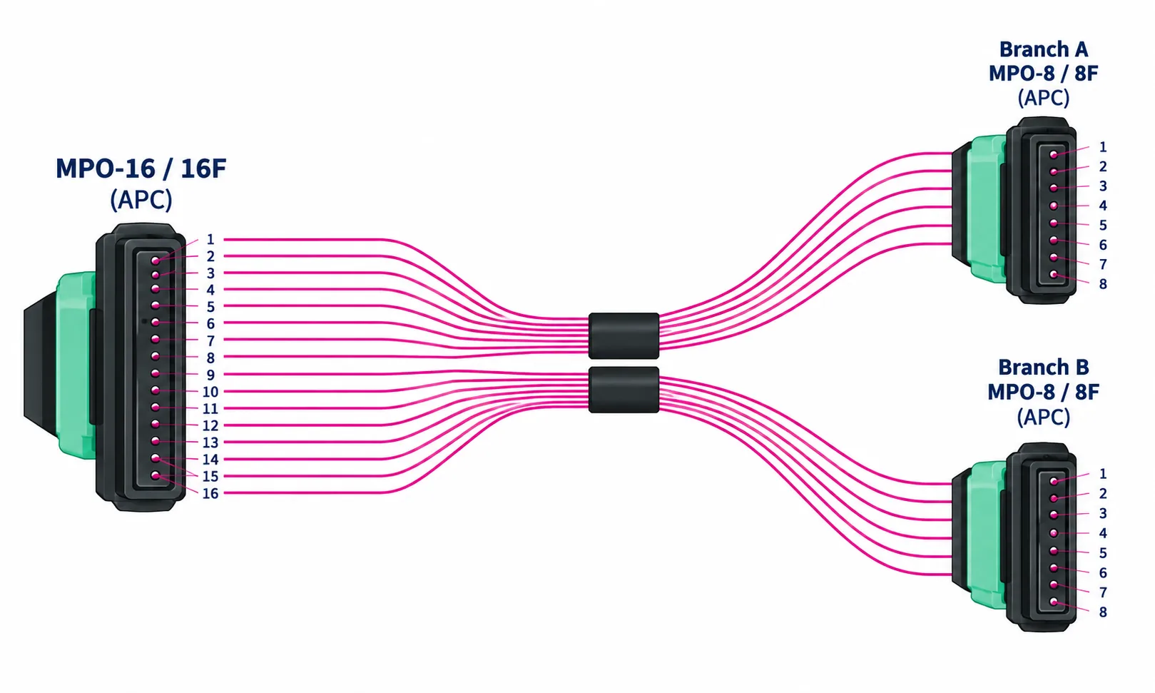
The sixteen fiber positions on the MPO-16 side are divided into two 8-fiber groups. Each branch should be mapped according to the connected optical modules and the intended transmit and receive lane arrangement.
For high-speed breakout links, polarity is not only a cable parameter. Connector orientation, guide-pin arrangement and end-to-end fiber mapping must all match the network topology.
Before production, confirm: transceiver part numbers, connector gender, APC interface, polarity, fiber mapping and breakout-leg identification.
Technical Specifications
| Product Type | MPO/MTP Breakout / Conversion Cable |
| Fiber Count | 16 Fibers → 2×8 Fibers |
| Fiber Type | OM4 Multimode 50/125 μm |
| Connector A | 1× MPO-16 / MTP-16 |
| Connector A Polish | APC |
| Connector B | 2× MPO-8 / MTP-8 |
| Connector B Polish | APC |
| Connector Gender | Female / Project-Specific |
| Polarity | Type B / Custom Fiber Mapping |
| Operating Wavelength | 850 nm / 1300 nm |
| Main Cable Diameter | Approx. 3.0 mm Configuration |
| Breakout Structure | Dual 8-Fiber MPO Branches |
| Jacket | LSZH / OFNP Options |
| Jacket Color | Magenta / Custom |
| Main Cable Length | Customized |
| Breakout Leg Length | Customized |
| Typical Application | Compatible 800G SR8 → 2×400G SR4 Breakout |
800G SR8 to 2×400G SR4 Breakout
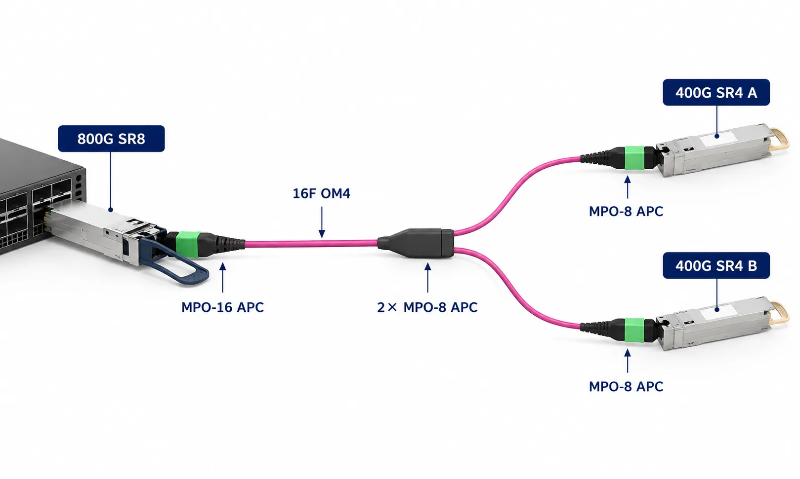
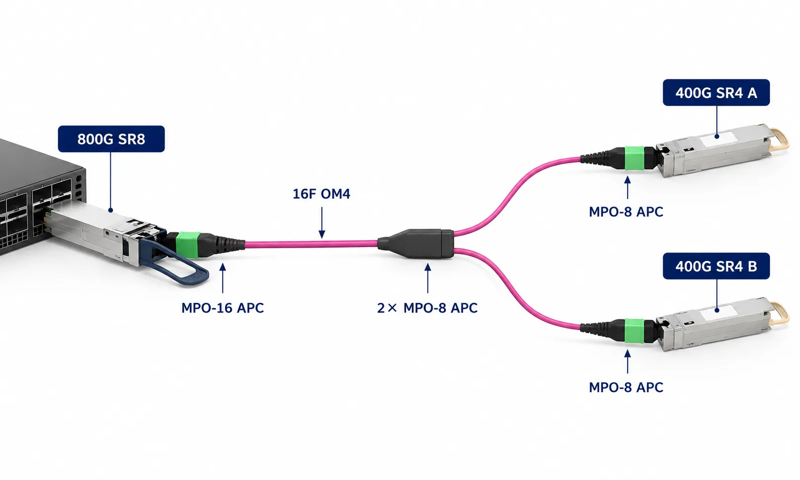
For compatible optical modules, an MPO-16 to 2× MPO-8 OM4 breakout cable can divide one 16-fiber SR8 interface into two independent 8-fiber SR4 connections.
A typical equipment-side architecture may use an 800G SR8 optical interface on the MPO-16 side and two 400G SR4 interfaces on the two MPO-8 branches. This allows bandwidth to be divided across two downstream links while retaining a compact pre-terminated fiber assembly.
Typical Connection:
800G SR8 → MPO-16 APC → 16F OM4 Breakout Cable → 2× MPO-8 APC → 2×400G SR4
Because 800G optical modules are available with different lane counts and connector formats, the transceiver model, connector polish, gender and polarity should always be verified before production.
Typical Applications


Custom Configuration Options
Configure the assembly around the actual transceiver interface, equipment ports and rack-routing requirements.
MPO-16 Connector
MPO-16 / MTP-16 APC with project-specific gender and key orientation.
Dual MPO-8 Branches
Two MPO-8 / MTP-8 APC branches with A/B identification for easier installation.
Polarity & Mapping
Type B or custom lane mapping according to the connected optical modules.
Cable & Breakout Length
Custom main cable length and breakout-leg length to match rack routing.
Jacket Options
LSZH / OFNP options with magenta or project-specific identification color.
Labels & Packaging
Customer PN, serial number, branch A/B labels, barcode and project-specific packaging.
How to Specify Your Cable
| Requirement | Example Configuration |
| Fiber Type | OM4 50/125 μm |
| Fiber Count | 16F → 2×8F |
| Connector A | MPO-16 APC Female |
| Connector B1 | MPO-8 APC Female |
| Connector B2 | MPO-8 APC Female |
| Polarity | Type B |
| Main Cable Length | 5 m |
| Breakout Length | 0.5 m |
| Jacket | LSZH |
| Labeling | Branch A / Branch B + Customer PN |
| Quantity | Project Quantity |
FAQ
Q: What is an MPO-16 to 2× MPO-8 breakout cable?
A: It is a 16-fiber breakout assembly that divides one MPO-16 interface into two independent 8-fiber MPO branches. Each breakout branch carries eight fibers.
Q: Can this cable be used for 800G to 2×400G breakout?
A: Yes, when the optical modules use a compatible SR8-to-dual-SR4 architecture. The exact transceiver connector, polish, gender and polarity should be verified before production.
Q: Does every 800G optical module use an MPO-16 connector?
A: No. 800G optical modules are available with different connector and lane architectures. Always confirm the actual module part number before selecting the cable.
Q: Should I choose APC or UPC for the MPO connectors?
A: The polish type must match the mating optical interface. This page is configured as APC-to-APC, but other interface requirements should be confirmed from the transceiver specification.
Q: How do I confirm MPO connector gender and polarity?
A: Check whether the mating equipment interface has guide pins and confirm the required end-to-end lane mapping. Sending the transceiver part numbers and topology is the safest way to specify the correct configuration.
Q: Can the two MPO-8 breakout legs be customized?
A: Yes. Main cable length, breakout-leg length, branch labels, jacket type and project identification can be configured according to the installation requirement.
Related MPO/MTP Resources
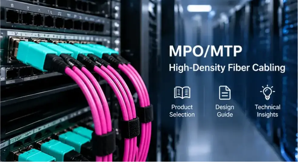
16 Fiber MPO/MTP OM4 Patch Cord - For MPO-16 to MPO-16 high-density parallel-optics connections.
MPO Data Center Cabling Design Guide: 40G–800G - Learn how fiber count, polarity, connector type and optical-module architecture affect MPO cabling design.
MPO Connectors for 400G and 800G - Understand where MPO-8, MPO-12 and MPO-16 interfaces are used in high-speed networks.
Need an MPO-16 to 2× MPO-8 Cable for Your Project?

Send the transceiver part numbers, connector gender, polish, polarity, main cable length, breakout-leg length and required quantity. DIMI can match the MPO-16 to dual MPO-8 configuration to the actual optical architecture before production.
Hot Tags: mpo-16 to 2× mpo-8 om4 breakout cable | 800g, China mpo-16 to 2× mpo-8 om4 breakout cable | 800g manufacturers, suppliers, factory