Choosing the right MPO cable comes down to five decisions: cable format, polarity method, fiber architecture, connector gender, and fiber mode. In practice, most engineers and procurement teams are comparing trunk cables, breakout (fan-out) cables, and patch cords, then confirming whether the link requires Type A, B, or C polarity and whether the fiber architecture is base-8 or base-12.
Getting any one of these wrong can result in a cable that physically mates but fails to pass traffic - or one that cannot mate at all. This guide walks through each decision in order, with deployment scenarios, so you can narrow down the right MPO cable before placing an order.

What Is an MPO Cable?
MPO stands for Multi-Fiber Push-On. An MPO connector terminates multiple fibers - typically 8, 12, 16, or 24 - into a single compact interface, which is why it has become the standard connector in high-density fiber optic networks. The connector format is defined internationally by IEC 61754-7 and in North America by TIA-604-5 (FOCIS 5).
An MPO cable is not simply "a cable with many fibers." It is part of a structured system. The cable type, polarity, gender, and fiber mode must all match the rest of the channel - from the patch panel or cassette to the transceiver port. Most selection errors happen when buyers treat these dimensions independently instead of as a linked set of decisions.
What Is the Difference Between MPO and MTP Connectors?
MPO is the generic connector format. MTP is a registered trademark of US Conec for a high-performance MPO-style connector. According to US Conec, the MTP connector includes engineered enhancements - such as a removable housing, a floating ferrule for better performance under mechanical load, and tighter tolerance guide pins - that improve optical and mechanical performance compared to standard MPO connectors.
The relationship is straightforward: every MTP connector is an MPO-style connector, but not every MPO connector is an MTP connector. In specifications and RFPs, it is worth being precise. If your application demands low insertion loss across multiple mating cycles - common in high-speed 400G and 800G parallel optics - specifying MTP Elite or a comparable enhanced-performance MPO connector can make a measurable difference in link budget. For a deeper comparison, see our MTP vs. MPO engineer's selection guide.
What Are the Main MPO Cable Types?
MPO cables fall into three primary categories based on what they connect and where they sit in the channel. Some deployments also use hybrid or conversion assemblies when the link needs to bridge different connectivity schemes.

MPO Trunk Cables
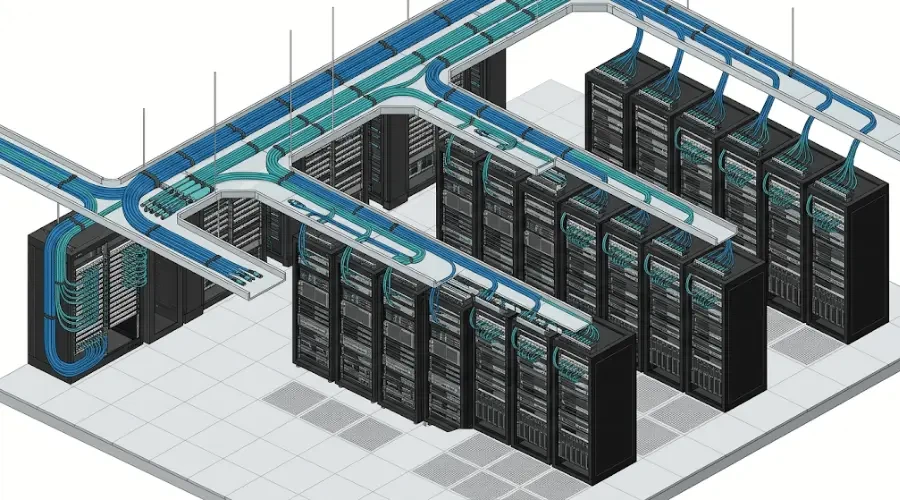
Trunk cables are the backbone option. They connect panels, cassettes, or structured cabling zones with an MPO connector on each end, carrying a high fiber count through a single assembly. In a typical spine-leaf data center interconnect, MPO trunk cables run between main distribution areas and equipment rows, consolidating what would otherwise be dozens of individual duplex connections into one managed cable path.
Use trunk cables when you are building structured backbone cabling between zones, connecting patch panels in different rows or floors, or supporting parallel optics links where both ends present an MPO interface. Browse MPO trunk cable options for common configurations.
MPO Breakout (Fan-Out) Cables
Breakout cables transition from a multi-fiber MPO connector on one end to individual duplex connectors - most commonly LC - on the other end. They are essential when your backbone uses MPO infrastructure but your endpoint equipment presents duplex ports.
A common real-world scenario: you have an MPO trunk running between distribution frames, but your top-of-rack switches use LC-based SFP+ or SFP28 transceivers. A breakout cable at the equipment end converts the MPO interface into individual LC connections without requiring a separate cassette or adapter panel. For more detail on selecting breakout configurations, see our MPO breakout cable selection guide.
MPO Patch Cords
Patch cords are shorter MPO-to-MPO interconnects used within racks, cabinets, or patching areas. They connect equipment ports to patch panels, or link adjacent panels within the same zone. Despite being physically simpler than trunks, patch cords must still match the channel's polarity method and connector gender. A polarity-correct trunk cable paired with an incorrect patch cord will produce a non-functional link.
Hybrid and Conversion Assemblies
Hybrid assemblies bridge different connectivity schemes within the same link. Examples include MPO-to-MPO conversion cables that change from base-12 to base-8, or multi-leg assemblies that split a higher-count MPO trunk into multiple lower-count MPO connections. These are typically used during infrastructure migration - for example, when a data center built on base-12 cabling needs to support new base-8 parallel optics transceivers without re-cabling the backbone.
MPO Polarity Types: Type A vs. Type B vs. Type C
Polarity determines whether the transmit (Tx) fibers at one end of a link correctly align with the receive (Rx) fibers at the other end. If polarity is wrong, the channel will not pass traffic. The TIA-568 standard defines three polarity methods - Method A, Method B, and Method C - each using a corresponding cable type.

Type A (Straight-Through)
A Type A cable routes Position 1 on one end to Position 1 on the other end, with a key-up connector on one end and key-down on the other. In duplex applications, the Tx-to-Rx flip must be handled elsewhere in the channel - typically by using different patch cord types at each end (an A-to-B patch cord on one side and an A-to-A patch cord on the other).
Type A works well in structured duplex backbone systems where the channel design already accounts for the required flip. It is a common choice in existing enterprise data center installations built before parallel optics became widespread.
Type B (Reversed)
A Type B cable uses key-up connectors on both ends, so Position 1 arrives at Position 12 (in a 12-fiber layout) at the far end. This configuration achieves the Tx-to-Rx flip within the trunk itself, which means the same type of patch cord can be used on both ends of the channel. According to Fluke Networks, this simplification is why Method B is most often recommended for both duplex and parallel optics deployments - it reduces the risk of installing the wrong patch cord type at one end.
For modern parallel optics links (40G, 100G, 400G, and 800G), Type B deserves strong consideration as the default polarity method unless your existing infrastructure is already standardized on Type A.
Type C (Pair-Flipped)
A Type C cable flips adjacent fiber pairs internally, so Position 1 arrives at Position 2 and vice versa. While this works for duplex applications, it does not support parallel optics well. Fluke Networks notes that Method C requires complex cross-over patch cords for 40G and 100G applications, and these components are not widely available. Unless you have a specific legacy reason to use Type C, it is generally best avoided in new deployments.
Base-8 vs. Base-12: Which Architecture Fits Your Network?
The fiber architecture - base-8 or base-12 - determines how many fibers the system is organized around and directly affects transceiver compatibility and fiber utilization.

Current parallel optics applications predominantly use 8 fibers: 4 transmitting and 4 receiving. This applies to 40GBASE-SR4, 100GBASE-SR4, 400GBASE-SR4, and 400GBASE-DR4 - all of which use 8-fiber MPO connectivity. According to Fluke Networks' 2026 guidance on 800G and terabit migration, the coming IEEE 802.3dj standard extends this further, supporting 800G over 8 single-mode fibers using 200 Gb/s per lane signaling.
Base-12 remains widely deployed in backbone cabling and duplex-oriented structured systems, where 12-fiber MPO connectors consolidate six duplex pairs into a single interface. If your infrastructure was built around 10G duplex links and you are maintaining that design, base-12 is still practical. But if you are deploying new parallel optics links for 400G QSFP-DD or 800G applications, base-8 alignment avoids wasted fibers and simplifies the channel design.
For environments running both legacy duplex and new parallel optics, conversion cassettes or hybrid assemblies can bridge base-12 backbone trunks to base-8 equipment interfaces - though each conversion point adds insertion loss that must be accounted for in the link loss budget.
Male vs. Female MPO Connectors: Why Gender Matters
MPO connectors come in two genders: male (with alignment pins) and female (without pins). The pins on a male connector ensure precise fiber-to-fiber alignment when two connectors mate. Active equipment - switches, transceivers, media converters - typically uses male MPO interfaces with pins built into the transceiver module.

This means any cable plugged directly into active equipment should have a female connector on the equipment side to avoid pin damage and ensure proper mating. It is one of the simplest checks in the selection process, but overlooking it leads to one of the most common procurement errors: ordering a polarity-correct, fiber-count-correct cable that physically cannot connect because the gender is wrong.
Before comparing multimode fiber grades or OS1 vs. OS2 single-mode options, confirm the gender requirement at each end of the cable. Adapters in patch panels typically mate female-to-female, so trunk cables connecting through adapters are usually male (pinned) on both ends. Patch cords connecting to equipment are usually female on the equipment side.
How to Choose the Right MPO Cable: A Step-by-Step Decision Path
Rather than evaluating all variables at once, work through the following sequence. Each step narrows the options before you reach the next.

Step 1: Identify the Application
Ask where the cable sits in the network. Backbone links between distribution frames typically call for trunk cables. Connections from MPO infrastructure to duplex equipment (such as LC-based switches) call for breakout cables. Short links within a single rack or between adjacent panels call for patch cords.
Step 2: Match the Fiber Architecture
Determine whether your transceivers and structured cabling are organized around base-8 or base-12. For new parallel optics deployments at 100G, 400G, or 800G, base-8 is the natural starting point. For legacy backbone consolidation or duplex systems, base-12 may be the existing standard.
Step 3: Select the Polarity Method
If you are building a new parallel optics channel, Type B polarity is the recommended starting point because it allows the same patch cord type on both ends. If you are extending an existing structured duplex system that already uses Type A, it may be more practical to continue with Type A rather than mix polarity methods within the same facility.
Step 4: Verify Connector Gender
Check every mating point. Equipment ports are usually male; cables going into equipment should be female. Trunk cables connecting through panel adapters are usually male on both ends. A mismatch at any point prevents a physical connection.
Step 5: Choose Fiber Mode and Performance Grade
Once format, architecture, polarity, and gender are confirmed, select single-mode or multimode fiber based on distance and application requirements. For high-speed links where the loss budget is tight, enhanced-performance connectors (such as MTP Elite grade) can reduce per-connection insertion loss and provide more headroom across multiple mating points.
Three Deployment Scenarios

Scenario 1: Spine-Leaf Data Center Backbone
A data center uses a spine-leaf architecture with 400G SR4 links between spine and leaf switches. Both sides present QSFP-DD transceivers with male MPO-8 interfaces. The right cable: a base-8 MPO trunk cable, Type B polarity, female connectors on both ends. No breakout is needed because both ends are MPO.
Scenario 2: MPO Backbone to LC Switch Ports
A campus backbone runs 12-fiber MPO trunks between buildings. At one end, the equipment uses 10G SFP+ transceivers with LC duplex ports. The right cable at the equipment end: a base-12 MPO-to-LC breakout cable, with polarity matching the trunk (typically Type A or Type B depending on the existing channel), and a female MPO connector on the trunk side.
Scenario 3: Direct Transceiver-to-Panel Connection
A network engineer needs to connect a 100G QSFP28 SR4 transceiver (male MPO-8 interface) directly to a patch panel port. The right cable: a short base-8 MPO patch cord, female on the transceiver side and male on the panel side, with polarity matching the rest of the structured cabling channel.
Common MPO Cable Selection Mistakes
Several errors come up repeatedly in MPO deployments, and most are avoidable if you follow the decision sequence above.
Ignoring polarity during procurement. Choosing a cable based on fiber count alone, without confirming whether the channel uses Type A, B, or C, frequently results in a cable that mates but does not pass traffic. Since pre-terminated MPO assemblies are often made to order and non-returnable, this mistake can cause project delays.
Ordering the wrong connector gender. A cable with correct polarity and fiber count but the wrong gender cannot physically connect. Always verify the gender at each endpoint before ordering.
Applying a base-12 assumption to a base-8 link. Older installation practices defaulted to 12-fiber MPO for everything. In environments now running 400G or 800G parallel optics, this leaves unused fibers in every connector and may require conversion modules that add loss and complexity.
Using "MTP" and "MPO" interchangeably in specifications. If your application requires enhanced-performance connectors, specifying "MPO" generically may result in receiving a standard-grade product. Conversely, specifying "MTP" when any standards-compliant MPO connector will suffice may unnecessarily limit your supplier options.
Installation, Inspection, and Testing

Once the correct cable is selected and installed, three practices help ensure the link performs as designed. These become especially important at 100G and above, where insertion loss budgets are tighter and each connector in the channel consumes a larger share of the available margin.
Inspect connector end faces before mating. Contamination on even one fiber in a 12-fiber array can degrade or block that channel. Use an MPO-specific inspection scope - a standard single-fiber probe will not cover the full ferrule.
Clean connectors with MPO-rated tools. Standard single-fiber cleaning tools do not address the wider ferrule surface of an MPO connector. Dedicated MPO cleaning devices are designed to cover all fiber positions in a single pass.
Verify polarity and measure insertion loss before going live. Tools such as the Fluke Networks CertiFiber Max can scan all fibers in an MPO connector, verify polarity, and measure loss across the link. Catching a polarity error or an out-of-spec connection before the link is put into production is far less expensive than troubleshooting it after deployment. For a broader overview of fiber deployment practices, see our fiber optic cable installation guide.
Frequently Asked Questions
What are the main MPO cable types?
The primary types are trunk cables (MPO-to-MPO for backbone links), breakout or fan-out cables (MPO-to-LC or similar for transitioning to duplex equipment), and patch cords (short MPO-to-MPO interconnects within racks or panels). Hybrid and conversion assemblies are used in migration scenarios or mixed-architecture environments.
What is the difference between MPO and MTP?
MPO is the generic multi-fiber connector format defined by industry standards. MTP is a registered trademark of US Conec for an enhanced-performance MPO-style connector with tighter tolerances and additional design features. Every MTP connector is an MPO connector, but not every MPO connector is an MTP.
Which polarity is better: Type A or Type B?
Neither is universally superior. Type B is often recommended for new parallel optics deployments because it allows the same patch cord type on both ends of the channel, reducing installation errors. Type A remains practical in existing structured duplex systems where the channel design already accounts for the required Tx-to-Rx flip.
Is Type C MPO polarity still used?
Type C can work in duplex applications, but it is generally not recommended for parallel optics. It requires specialized cross-over patch cords that are not widely stocked, which adds complexity and procurement risk.
How do I know if I need a male or female MPO connector?
Check the interface on the active equipment. Transceivers and switch ports typically use male (pinned) MPO interfaces, so the cable plugged into them should be female (unpinned). Adapters in patch panels usually mate female-to-female, so trunk cables connecting through adapters are typically male on both ends.
Is base-12 MPO cabling still relevant?
Yes. Base-12 remains widely deployed in backbone and duplex-oriented structured cabling. However, most current parallel optics transceivers (40G, 100G, 400G) use 8 fibers, and the upcoming IEEE 802.3dj standard supports 800G over 8 single-mode fibers. New parallel optics deployments increasingly favor base-8 for better fiber utilization.
What MPO configuration do I need for 400G?
Most 400G parallel optics applications - including 400GBASE-SR4 and 400GBASE-DR4 - use 8 fibers (4 Tx + 4 Rx) with an MPO-8 or MPO-12 connector. Type B polarity is the standard recommendation. Check your specific transceiver datasheet to confirm the required connector type, fiber count, and end-face polish (UPC or APC).
Can I connect a base-12 trunk to base-8 equipment?
Yes, but you will need a conversion cassette or hybrid harness to bridge the two architectures. Each conversion point adds insertion loss, so factor this into your link budget calculation. For new builds, choosing a matching base architecture from the start avoids this overhead.