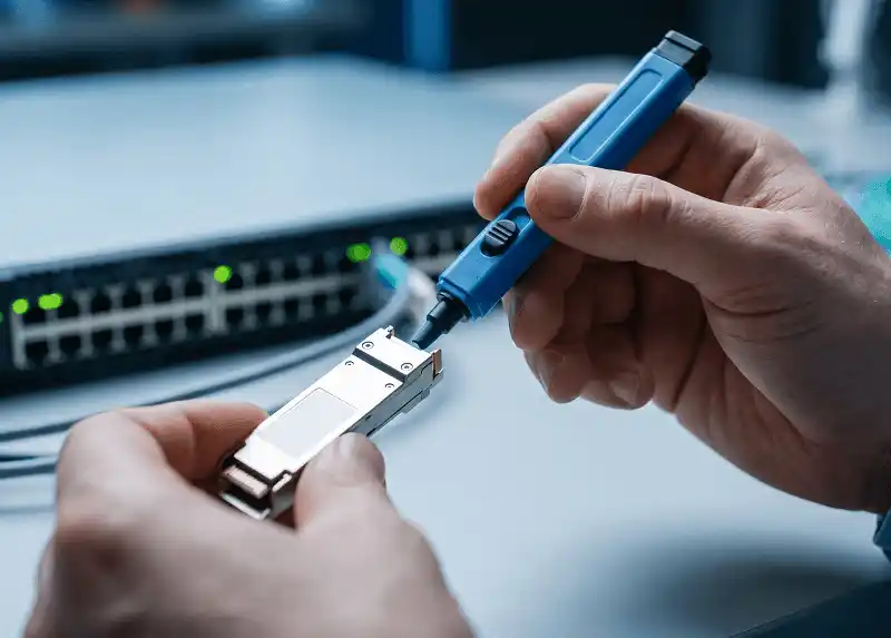
If you work with optical transceivers, switches, or fiber test setups, a fiber loopback cable is one of the most practical tools you can keep on hand. It creates a closed optical path by routing the transmit (Tx) signal back into the receive (Rx) side of the same device - making it useful for quick port verification, transceiver troubleshooting, and local fault isolation during network testing.
But the real question most engineers have is not just "What is a fiber loopback cable?" - it is "What can it actually prove, what are its limits, and how do I pick the right one for my setup?" This guide covers all of that: testing scope, step-by-step procedures, selection criteria, common mistakes, and when a loopback test is not enough.

What Is a Fiber Loopback Cable?
A fiber loopback cable - also called a loopback plug, loopback adapter, or fiber loopback module - is a short fiber optic assembly that connects the transmit and receive paths of an optical port so the signal returns to the same device. It is not a production cable. Its sole purpose is diagnostic: creating a closed loop so you can verify whether a port or transceiver is functioning locally, without relying on remote equipment or installed cabling.
Quick answer: A fiber loopback cable is a testing accessory that routes an optical transmit signal directly back into the receive port of the same device. It is used to verify transceiver and port functionality in a controlled local test, helping engineers isolate whether a fault is inside the device or somewhere else in the link.
Fiber loopback products are available in single-mode and multimode versions, and in connector formats such as LC, SC, and MTP/MPO. That variety makes them applicable across data center, enterprise, and lab environments where different optics and connector ecosystems coexist. Loopback connectors are typically compliant with IEC, TIA/EIA, and other industry specifications relevant to fiber optic interconnects.

What Does a Fiber Loopback Cable Actually Test?
A fiber loopback cable helps verify whether an optical port or transceiver can transmit and receive properly in a controlled local test. In practical terms, you use it to check whether a port comes up, whether the optic responds normally, and whether Tx and Rx behavior looks healthy under basic diagnostics.
Here is what a loopback test can confirm:
- The transceiver laser is transmitting within its expected power range.
- The receive side detects optical signal and the port shows link-up status.
- DOM/DDM readings - including Tx power, Rx power, laser bias current, and temperature - fall within the thresholds defined by the transceiver manufacturer. (These diagnostic parameters are standardized under the SFF-8472 specification published by the SNIA SFF Committee.)
Here is what a loopback test cannot prove:
- That your full end-to-end fiber path is problem-free.
- That the remote device, installed cabling plant, or connectors in the channel are healthy.
- That the link will perform correctly at full production traffic load.
This distinction matters. A successful loopback test confirms the local port and optic are operational. It does not validate the whole channel. That is why loopback testing works best as an isolation method: if the loopback passes, shift attention to cabling, remote ports, or configuration. If it fails, the problem is likely in the local optic, port, or test setup.
Fiber Loopback Cable vs. Patch Cord vs. Optical Attenuator
These three items appear in fiber testing contexts, but they serve different purposes and should not be confused.
A fiber loopback cable is built specifically to return the signal to the same device for local testing. A fiber patch cord is designed to connect separate devices in a live or test network. In some situations, a patch cord can be temporarily bent into a loop for a quick test, but it is fundamentally a connection cable - not a purpose-built loopback module with controlled insertion loss.
An optical attenuator addresses a different problem entirely. It reduces optical power when the receive side may be exposed to too much signal. According to multiple transceiver vendor guidelines, high-power or long-reach optics - such as those rated for 40 km or 80 km single-mode links - may output enough power to damage a receiver when the signal is looped directly back without attenuation. In these cases, an attenuator is used alongside the loopback cable, not instead of it.

A practical rule of thumb:
- Loopback cable: Use when you want a fast local verification of a port or transceiver.
- Patch cord: Use when you need to connect devices, or when a temporary loop is acceptable and you understand the insertion loss trade-off.
- Attenuator: Use when receive power may be too high for the optic under test - especially during loopback testing of long-reach single-mode transceivers.
How to Perform a Fiber Loopback Test
A good loopback test is more than plugging something in. It starts with knowing what you want to confirm and ends with structured interpretation.
Step 1: Define the test objective
Before connecting anything, decide what you are trying to verify. Are you checking whether a newly received transceiver is functional before deployment? Isolating whether a link fault is local or remote? Validating a suspect port after a firmware upgrade? The objective shapes which indicators you monitor and how you interpret the result.
Step 2: Match the loopback to your hardware
Choose a loopback cable that matches the optic or port under test in three dimensions: connector type, fiber mode, and fiber count.
- Connector type: LC for most SFP/SFP+ duplex optics, SC in some legacy or PON environments, and MTP/MPO for parallel-fiber transceivers such as QSFP+ (40G) and QSFP28 (100G). A connector mismatch is an immediate blocker.
- Fiber mode: Use single-mode (OS2, 9/125 µm) loopbacks for single-mode optics and multimode (OM3/OM4, 50/125 µm) for multimode optics. Mismatching modes will produce unreliable results or no link-up at all.
- Fiber count: Duplex loopbacks work for standard two-fiber transceivers. For 40G SR4 or 100G SR4 parallel optics, you need an MTP/MPO loopback module with the correct fiber count (typically 8 or 12 fibers) and polarity configuration.
Step 3: Clean the end faces and connect the loopback
Insert the transceiver (if not already installed), then connect the loopback cable between the Tx and Rx sides. Before mating, inspect and clean the connector end faces. This step is not optional. According to the IEC 61300-3-35 standard, contamination on fiber end faces is one of the most common causes of signal degradation and misleading test results. Even new connectors out of packaging can carry dust or residue from protective caps.
Also avoid sharp bends in the loopback fiber. Excessive bend radius introduces bend loss that can skew your readings.
Step 4: Check power levels before running the test
If you are testing long-reach or high-power optics - for example, a 10GBASE-LR transceiver rated for 10+ km - check whether the Tx output power exceeds the receiver's maximum input power. When the signal is looped back with minimal loss, the full Tx power hits the Rx directly. For short-reach multimode optics this is typically not a concern, but for high-power single-mode transceivers it can overload or even damage the receiver photodiode. In these cases, insert an inline optical attenuator between the Tx output and Rx input to bring the received power within the transceiver's safe operating range.
Step 5: Run diagnostics and observe the right indicators
Once the optical loop is closed, observe the device diagnostics. Depending on your platform, the key indicators include:
- Link status: The port should show link-up. If the link LED stays dark or the port shows "down," something is wrong with the optic, port, or loopback itself.
- Tx power: Should be within the transceiver vendor's specified range (typically listed in the transceiver datasheet).
- Rx power: Should be detectable and within the receiver sensitivity and overload thresholds. In a loopback configuration, Rx power will typically be close to Tx power minus the loopback's insertion loss.
- Laser bias current and temperature: Abnormal values here may indicate a degraded or failing transceiver, even if the link is up.
These parameters are accessible via the transceiver's Digital Diagnostic Monitoring (DDM) interface, as defined in the SFF-8472 specification. Most managed switches and routers expose DDM readings through their CLI or management software.
Step 6: Interpret results and isolate the fault
If the loopback test passes - link comes up, DOM values are within spec - the local optic and port are very likely healthy. You can then shift troubleshooting to the installed cabling, far-end device, or configuration.
If the test fails, replace one variable at a time: try a known-good transceiver, try a different loopback cable, verify the port configuration, or move the test to a different port on the same switch. This structured elimination is where loopback testing delivers its real diagnostic value.
Real-world example: A network engineer receives a trouble ticket reporting an SFP+ port that will not establish a link on a production switch. Before pulling cable or dispatching a technician to the remote site, they insert a single-mode LC loopback into the suspect port. The port shows link-up, and DOM readings show Tx power at −2.1 dBm and Rx power at −2.8 dBm - both within spec. The loopback test passes, which rules out the local transceiver and port. The engineer now knows the fault lies somewhere in the fiber run, the patch panel, or the far-end equipment - saving hours of guesswork.

How to Choose the Right Fiber Loopback Cable
Choosing the right loopback cable comes down to compatibility with your hardware and awareness of the testing environment. Here is a selection checklist:
| Selection Criterion | What to Match | Common Options |
|---|---|---|
| Connector type | The physical port interface of the device under test | LC, SC, FC, MTP/MPO |
| Fiber mode | The optic's fiber specification | Single-mode (OS2 9/125 µm), Multimode (OM3/OM4 50/125 µm) |
| Fiber count | Duplex vs. parallel optics | 2-fiber (duplex), 8-fiber, 12-fiber, 24-fiber (MPO/MTP) |
| Polarity (for MPO) | Tx-to-Rx fiber mapping in multi-fiber connectors | Type A, Type B (most common for SR4 transceivers) |
| Insertion loss | Acceptable loss for accurate diagnostics | Typical ≤ 0.5 dB (duplex), ≤ 1.0 dB (MPO) |
| Attenuation needed? | Whether Tx power may overload Rx in loopback | Not needed for short-reach MM; may be needed for long-reach SM |
A few additional notes on selection:
- For high-density 40G and 100G environments using QSFP+ or QSFP28 parallel optics, you need an MTP/MPO loopback module - not a duplex LC loopback. The fiber count (typically 8 for 40G SR4, 12 for some 100G configurations) and polarity must be correct, or the transceiver will not link up.
- If you regularly test both single-mode and multimode equipment, keep both types on hand. A multimode loopback on a single-mode port (or vice versa) will usually produce no link, or unreliable DOM readings that can mislead your diagnosis.
- For transceivers operating at different speeds - 1G, 10G, 25G, 100G - the loopback itself does not need to be "rated" for a specific data rate. The key is that the fiber type and connector match the transceiver. The data rate compatibility is determined by the optic, not the passive loopback cable.
When Loopback Testing Is Not Enough
A loopback test is a powerful first step, but it has clear boundaries. Knowing when to move beyond it is just as important as knowing how to run one.
Consider escalating to other test methods when:
- You need end-to-end link validation. A loopback only confirms local behavior. To verify the full fiber path - including connectors, splices, and the installed cable plant - you need an optical time-domain reflectometer (OTDR) or a bi-directional insertion loss test.
- The loopback passes but the production link still fails. This usually points to a problem in the cabling infrastructure, a dirty connector at a patch panel, a bad splice, or a far-end device issue. An OTDR can help pinpoint the location of the fault along the fiber run.
- You suspect marginal performance rather than a hard failure. A loopback test is a go/no-go check. It does not measure channel-level parameters such as total insertion loss across the full link, return loss at each connection point, or chromatic/modal dispersion.
- You are commissioning a new fiber installation. Pre-deployment acceptance testing typically requires Tier 1 (insertion loss) or Tier 2 (OTDR) testing per TIA-568.3 or equivalent standards - not just a loopback check at each end.
Think of loopback testing as the fastest way to answer a narrow question: "Is this port and optic basically working?" If the answer is yes and you still have a problem, it is time to look deeper into the link.
Common Mistakes and Precautions
Assuming a loopback test validates the entire network. It does not. It is excellent for local isolation, but it tells you nothing about the fiber run, intermediate patch points, or far-end equipment. Treating a passed loopback as proof that "the network is fine" is the most common misinterpretation.
Skipping connector cleaning. Dirty end faces affect signal quality and produce misleading DOM readings. Research published by NTT Advanced Technology has found that connector contamination accounts for four of the top five causes of fiber network failures. The IEC 61300-3-35 standard provides detailed inspection and cleanliness grading criteria - follow them before every test.
Ignoring receive power on high-power optics. Looping a long-reach single-mode transceiver back into itself without attenuation can push received power above the receiver's maximum input threshold. This risks damaging the photodiode or triggering receiver overload alarms. Always check the transceiver datasheet for maximum Rx input power and compare it against the expected loopback Rx level.
Using the wrong fiber mode or connector type. A multimode loopback on a single-mode port - or an LC loopback on an MTP/MPO transceiver - will produce no link or garbage readings. Always verify the match before connecting.
Blaming the device when the loopback itself is faulty. A damaged connector housing, broken internal fiber, or excessive bend in the loopback cable can create test failures that look like device issues. If a port fails a loopback test, try a known-good loopback before condemning the transceiver or port.
Where Fiber Loopback Cables Are Most Useful
Fiber loopback cables see the most use in these scenarios:
- Pre-deployment bench testing: Verifying that newly received transceivers are functional before installing them in production switches. This is standard practice in data centers that handle large volumes of optics from multiple vendors.
- Transceiver troubleshooting: When a link goes down and you need to quickly determine whether the problem is the local optic/port or something else in the path.
- Port burn-in and qualification: Equipment manufacturers and testing labs use loopback modules during quality assurance to confirm that every port on a switch or router card operates within spec before shipment.
- Quick fault isolation in live environments: When a data center technician needs a fast first-pass diagnostic before escalating to cable plant testing or dispatching a remote-site visit.
- Lab and staging environments: Where engineers frequently reconfigure optical links and need a reliable way to verify port health between changes.
Frequently Asked Questions
Is a fiber loopback cable the same as a patch cord?
No. A fiber loopback cable is designed to route the signal back to the same device for testing purposes. A fiber patch cord connects two separate devices in a network. While a patch cord can sometimes be bent into a temporary loop, it is not built as a loopback module and may introduce uncontrolled insertion loss.
Can I use a loopback cable on single-mode optics?
Yes, but you must use a single-mode loopback (OS2, 9/125 µm). Using a multimode loopback on a single-mode transceiver will typically result in no link or unreliable readings. Also check whether the single-mode optic is high-power - if so, you may need an attenuator to prevent receiver overload during the test.
Do I need an attenuator for loopback testing?
It depends on the transceiver. Short-reach multimode optics (e.g., 10GBASE-SR) generally do not need attenuation for loopback testing. Long-reach single-mode optics (e.g., 10GBASE-LR, 10GBASE-ER) often output enough power that the looped-back signal exceeds the receiver's maximum input threshold. In those cases, an inline attenuator is recommended to bring Rx power within the safe operating range specified in the transceiver datasheet.
Does a successful loopback test prove the entire link is healthy?
No. A loopback test only confirms that the local port and transceiver can transmit and receive properly in a closed test path. It does not validate the installed fiber cabling, intermediate connectors, splices, or the far-end device. For full link validation, additional testing such as insertion loss measurement or OTDR analysis is required.
What DOM/DDM readings should I check during a loopback test?
At a minimum, check Tx power, Rx power, laser bias current, and module temperature. Compare each value against the alarm and warning thresholds defined in the transceiver's datasheet or exposed via the SFF-8472 diagnostic interface. If Tx power is within spec but Rx power is abnormally low during loopback, suspect a dirty connector, damaged loopback fiber, or fiber mode mismatch.