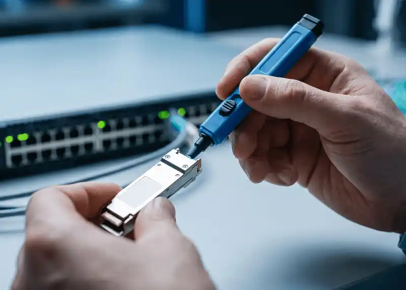
When a QSFP-DD link is down, flapping, or accumulating errors, resist the urge to swap the module first. Start by capturing the current state, then work outward in a fixed order: physical path, module recognition, speed and FEC, breakout mapping, optical telemetry, thermal conditions, and finally controlled isolation. Most "bad transceiver" tickets are resolved before the isolation step.
A QSFP-DD connection is a system, not a component. The transceiver can be perfectly healthy while the link still fails because of switch firmware, a port-group profile, the wrong fiber interface, a mismatched FEC mode, a misrouted patch panel, the remote endpoint, or the cage's thermal environment. This guide separates those domains so you can tell them apart with evidence rather than guesswork.

Scope, Assumptions, and Limitations
This workflow applies to common 400G QSFP-DD and 800G QSFP-DD800 deployments in data centre and DCI environments. Exact commands, alarm thresholds, FEC modes, application codes, and breakout rules depend on your switch platform, network operating system, module type, and software release - always confirm against the vendor documentation for your exact combination.
The diagnostic sequence below is written for network and optical engineers who already work with host and media lanes, DOM telemetry, and FEC counters. Where a term is likely to be read differently across teams, it is defined at first use. The three field patterns near the end are anonymised composite scenarios drawn from recurring failure modes, not transcripts of individual incidents; treat them as illustrations of diagnostic reasoning rather than as case records.
QSFP-DD Troubleshooting at a Glance
Use the symptom to choose your first three checks. The right-hand column is the fault domain most likely to be responsible, not a diagnosis.
| Symptom | Check first | Likely fault domain |
|---|---|---|
| Module not detected | Seating, EEPROM readability, host firmware support | Port, module coding, power class, CMIS handling |
| Module detected, link down | Speed, FEC, application selection, remote port state | Configuration, fiber path, incompatible PMD |
| Link flapping | RX power trend, connector condition, FEC counters, temperature | Marginal optical budget or thermal instability |
| High corrected FEC errors | Per-lane RX power, fiber loss, end-face condition | Reduced optical or electrical margin |
| CRC or uncorrected errors | FEC mode agreement, lane errors, cable, remote endpoint | Signal integrity or configuration mismatch |
| Some breakout ports missing | Breakout profile, port group, lane mapping | Host configuration or cable mapping |
| Temperature alarm | Module thresholds, airflow, heatsink contact | Cooling design, module power class, blocked airflow |
| Works in one port only | Port profile, port hardware, cage position | Port-specific configuration or hardware |
The Seven-Step Sequence
- Capture the current evidence before touching anything.
- Classify the symptom into one of the fault families above.
- Verify the physical and optical path, including both end faces.
- Check module recognition and CMIS state, stage by stage.
- Verify speed, FEC, and breakout at both ends.
- Review telemetry: DOM, BER, per-lane errors, power, and temperature.
- Isolate one variable at a time with known-good components.
A Short Decision Path
If you only remember one branch structure, remember this one:
- Does the host see the module at all?
- No → reseat, check port power and platform support, then try a known-good module in the same port. If that also fails, the port is the suspect. Go to Step 4.
- Yes → can the host read the EEPROM and select an application?
- No → coding, firmware, or module fault. Go to Step 4.
- Yes → is the interface up?
- No → speed, FEC, application, breakout, or optical path. Go to Steps 3 and 5.
- Yes, but with errors → is RX power inside the module's advertised range on every lane?
- No → clean and re-inspect, then verify the fiber route. Go to Step 3.
- Yes → look at temperature trend and FEC trend over time. Go to Steps 6 and 7.

Step 1 - Capture the Current State Before You Change Anything
Restarting an interface, clearing counters, upgrading firmware, or swapping several components at once will often restore the link temporarily - and destroy the evidence that would have identified the root cause. The same fault then returns during the next traffic peak, with nothing recorded to work from.
Record the Module, Port, and Software Details
Capture the switch vendor and model, NOS release, interface name, administrative and operational state, configured and operational speed, breakout profile, FEC configuration, module manufacturer, part and serial number, module firmware revision, reported CMIS revision, advertised applications, the remote-end equipment and module, the time of first failure, and any configuration or firmware change in the preceding days.
What good looks like. Every field above is populated from live output, not from an asset database. An entry in the module inventory is not proof that the module is ready for traffic - a host can detect presence and still fail to read the EEPROM, select an application, activate the data path, or enable the transmitter. Those are five distinct states, and Step 4 separates them.
Save DOM, FEC, and Error Counters
Digital optical monitoring (DOM) is the module's self-reported telemetry: temperature, supply voltage, transmit bias current, and per-lane transmit and receive optical power, each with its own warning and alarm thresholds. Collect all of it from both ends, together with corrected and uncorrected FEC codeword counts, pre-FEC BER, post-FEC BER where available, and CRC, symbol, alignment, and interface error counters.
Available fields differ by module class. Coherent optics typically expose additional metrics that direct-detect modules do not - OSNR and ESNR estimates, chromatic dispersion, differential group delay, carrier frequency offset, and polarization-related figures. Arista documents this difference explicitly in its EOS transceiver performance monitoring guide, where the DOM output for a 400GBASE-ZR interface carries a very different field set from a 100GBASE-DR interface.
Check the Remote End
A local port can report perfectly normal TX power while the far end receives too little. The local interface can also be configured correctly while the remote port runs a different speed, FEC mode, or breakout application. Asymmetric optical loss and asymmetric configuration are two of the most common reasons a "one-sided" investigation stalls. Collect the same data set from both ends whenever access allows.
Step 2 - Classify the Symptom
Module Not Detected
"Not detected" is not one condition. It can mean the host senses no module at all, senses the module but cannot read its EEPROM, reads incomplete or corrupted vendor data, sees the module stuck in a low-power or initialization state, actively rejects it as unsupported, reads it fine but selects no application, or reaches module-ready state without activating the data path.
Start with physical seating and the host's module inventory, then move to EEPROM, power, fault, and state information. A CMIS version mismatch is one possible cause among several - compatibility also depends on the host implementation, the module's application advertisement, its power class, vendor qualification, and platform firmware.
The QSFP-DD form factor provides eight high-speed host lanes, while management behaviour is defined by the Common Management Interface Specification (CMIS), now maintained by the Optical Internetworking Forum. The current published revision is CMIS 5.4 (released May 2026; verified July 2026), but fielded modules and switches frequently implement earlier revisions or partial subsets, so the revision a module reports matters more than the revision the specification has reached. If you need background on the form factor itself before working through host lane and application behaviour, our QSFP-DD technical overview covers the lane structure and variants.
Module Detected but Link Down
When the module is visible but the interface stays down, the fault is usually configuration or optical path rather than a failed EEPROM. Verify that both ends run the same intended speed and support the selected PMD, that FEC settings match the application, that the correct application is selected, that the transmitter is enabled, that fiber and connector type match the module, that the remote port is enabled, that RX power sits inside the module's specified range, and that breakout is configured consistently at both ends.
What an abnormal result suggests. If RX power is in range on every lane and both ends agree on speed, FEC, and application, but the link still will not come up, the problem has moved into host-side lane behaviour or application activation - return to Step 4 rather than replacing fiber.
Link Flapping
Intermittent links are diagnosed from trends, not from a single instantaneous reading. Watch the RX power trend, per-lane power imbalance, corrected and uncorrected FEC counters, interface reset counts, module and port temperature over time, and correlate against cable movement, connector condition, firmware release notes, and remote-end events.
Two patterns carry most of the diagnostic weight. A link that runs cleanly when cold and starts flapping after warm-up or under load points to thermal and power behaviour. A link that fails when a cable is touched or a panel door is closed points to seating, strain, or the physical path.
Link Up with High FEC or CRC Errors
A link can be operational and still be running with almost no margin. Corrected FEC events show the FEC engine repairing errors in real time; they are not, on their own, proof of a failed module. What matters is the rate, the direction of travel, and the distance from this link's own baseline.
Uncorrected errors, post-FEC errors, packet loss, or rising CRC counters indicate something more serious. Before escalating, correlate them with RX power, per-lane data, temperature, recent cable work, remote-end counters, and configuration changes - a "module problem" that started the same afternoon someone re-terminated a patch panel usually is not a module problem.
Only Some Breakout Ports Work
Polarity is the usual first guess and often the wrong one. Confirm that the switch supports the requested breakout on that specific physical port, that the port group is configured correctly, that both ends use the same lane mode, that the cable is built for the required breakout, that lane mapping matches the module and remote ports, that the module advertises the required application, and that the remote child ports are enabled at the correct speed.
Many switches apply breakout configuration to a group of physical ports rather than to a single port, so a change intended for one interface can silently constrain its neighbours. On the cabling side, the MPO breakout cable selection guide walks through fiber counts and leg assignments, which is where mismatches between a 4×100G expectation and an 8×100G assembly usually surface.
Step 3 - Verify the Physical and Optical Path
Confirm the Connector and Fiber Type
QSFP-DD describes a module form factor, not a single optical interface. Depending on the module, the media side may present MPO-12, MPO-16, duplex LC, dual CS, SN, a passive copper DAC, an active copper cable, or an AOC.
Polish type varies with it, and this is where assumptions cause the most wasted time. Rather than generalising by PMD family, check the specific part number. Cisco's QSFP-DD800 data sheet is a useful worked example: QDD-8X100G-FR requires APC MPO patch cords, while QDD-2X400G-FR4 in the same portfolio uses two duplex LC connectors - two 800G modules, two entirely different cabling requirements. Before you clean a single patch cord, identify the exact module part number and open its data sheet.
Then confirm fiber type (multimode or single-mode), connector type, polish, fiber count, polarity, maximum reach, and the patch-panel architecture in between. If the deployment mixes MPO and MTP hardware across panels, the MTP vs MPO selection guide explains where the two differ in practice.
Inspect, Clean, and Re-inspect Both Ends
Inspect both mating surfaces before reconnecting them. A practical sequence:
- Disconnect the link safely and cap what you are not working on.
- Inspect the module interface and the cable connector under a scope.
- Clean with a tool designed for that connector and ferrule type.
- Re-inspect the end face.
- Reconnect only once both surfaces pass.
- Repeat at every patch panel and at the remote endpoint.
A dust cap does not guarantee cleanliness, and a contaminated connector will transfer debris to a clean mating surface on first insertion. For a defensible pass/fail criterion rather than a visual judgement call, IEC 61300-3-35:2022 specifies the zones, defect classifications, and microscope requirements used to determine whether an end face is fit for use, and covers rectangular ferrules as well as cylindrical ones. Note that its scope is the whole contact area, not just the fiber zones - on MT ferrules, contamination between fibers is easy to miss and entirely capable of causing the single-lane faults described in Step 6.
Cable Routing and Mechanical Stress
Verify that the module latch is fully engaged, that the cable is not pulling downward or sideways on the module, that there are no crushed sections or tight bends, that patch cords are not trapped behind panels or cable management arms, that the bend radius follows the cable manufacturer's specification, that DAC and AOC lengths are within platform support, and that cable orientation is correct.
Bend radius is specification-dependent - a single universal number applied across every fiber and assembly type will be wrong somewhere in the estate.
Compare TX and RX Power at Both Ends
Two endpoints are what separate a transmitter problem from a fiber-path problem. Two readings, two conclusions:
- Source TX normal, destination RX low, reverse direction normal. Loss in one direction of the optical path: contamination, a damaged fiber, a poor splice, or a wrong patch-panel route. Understanding how those add up is the subject of our note on insertion loss in fiber networks.
- Source TX low on one lane, destination RX low on the same lane, fiber inspection clean. The source module or its host-side lane is now the leading suspect.
Always compare readings against the module data sheet and the module's own advertised thresholds, not against a value remembered from a different platform.
Step 4 - Check Module Recognition and CMIS State
Separate Presence, Module State, and Data Path State
Collapsing everything into "the switch doesn't like the module" hides the useful information. Five distinct stages, each failing for different reasons:
- Presence detected - the host senses an inserted module.
- EEPROM readable - vendor, part number, capabilities, and management pages can be read.
- Module ready - initialization and power-up have completed.
- Application selected - the host has chosen a supported host-lane and media-lane application. A host lane is an electrical channel between the switch ASIC and the module; a media lane is an optical channel on the fiber side. They do not always map one to one.
- Data path active - transmit and receive paths are enabled for traffic.
Recent Cisco IOS XR releases surface module state and data path state directly in the optics controller output, which makes this distinction visible rather than inferred - see Configuring Controllers for Cisco 8000 Series routers.
Read the EEPROM and Advertised Applications
Check whether the host can read vendor name, part number, serial number, firmware version, CMIS revision, supported applications, host and media lane counts, power class, temperature and voltage, module and data-path states, and fault and alarm flags.
Incomplete or inconsistent EEPROM output narrows the field quickly: it points to unsupported host parsing, a module firmware problem, a management-interface communication fault, incorrect coding, or genuine hardware failure. Comparing against a known-good module of the same part number in the same port usually distinguishes the first two from the last.
Verify Host Firmware and Qualified Support
Check the platform compatibility matrix, the minimum switch software release, known issues in the release notes, the required port profile, supported FEC modes, breakout restrictions, maximum module power, and qualified third-party coding.
Firmware upgrades during an active outage are a common way to lose the fault. Record the current version first, confirm that the target release actually addresses the observed problem, and confirm the rollback path before committing.
Treat Third-Party Module Warnings Carefully
A third-party module can be electrically and optically correct yet rejected on coding or qualification policy. It can equally be accepted while some monitoring fields stay unavailable, which quietly removes the telemetry you need for Step 6.
Confirm the exact switch model, NOS version, required vendor code, module firmware, supported application, FEC requirement, DOM support, and the supplier's qualification evidence. Commands that force acceptance of unsupported transceivers exist on most platforms, but their support and warranty consequences differ significantly between vendors and sometimes between platforms from the same vendor - check the written policy that applies to your specific contract rather than assuming an industry norm.
Step 5 - Verify Speed, FEC, and Breakout Configuration
Match Speed and Lane Mode at Both Ends
Confirm the intended link mode: 1×400G, 2×200G, 4×100G, 1×800G, 2×400G, or 8×100G. The module, host port, cable, and remote endpoint must all support the same application. Mechanical fit proves nothing about electrical or application compatibility - a module that seats cleanly in a cage can still advertise no application the host is willing to select.
Select the Correct FEC for the Application
There is no universal FEC setting for 400G QSFP-DD. FEC behaviour depends on the Ethernet PMD, whether the optics are direct-detect or coherent, the host-side electrical interface, the media-side optical interface, the module DSP, the switch implementation, and the breakout mode.
Coherent applications make the difference concrete. Arista's EOS Ethernet Ports documentation describes both Concatenated FEC (C-FEC) - the default specified for 400GBASE-ZR coherent transceivers under CMIS 4.0 - and Open FEC (O-FEC), which offers higher coding gain and tolerates a substantially higher pre-FEC BER, selected with an explicit error-correction encoding command. That is a different world from the FEC used by common direct-detect 400G Ethernet PMDs, and applying assumptions from one to the other produces links that come up and then fail under load.
Once you have saved the original counters, change configuration in a defined order: apply the verified configuration, clear the relevant counters, bring the link up, observe fresh FEC, CRC, and lane statistics, and compare both ends over the same time window. Comparing a freshly cleared counter at one end against a six-month-old counter at the other tells you nothing.
Verify Breakout and Port-Group Restrictions
Check whether the platform requires a chassis-level profile, a port-group profile, a reboot, a specific cable type, a particular lane order, a supported module application, or matching configuration at both ends. When only one or two child ports fail, compare each lane pair, cable leg, and remote interface independently rather than treating the breakout as a single object.
Step 6 - Interpret DOM, BER, and Per-Lane Errors
Use the Module's Advertised Thresholds
Avoid universal claims: that every module must stay below one fixed temperature, that one voltage range applies to all modules, that a specific bias-current increase always proves end of life. None of these survive contact with a mixed estate.
Use instead the module's own warning and alarm thresholds, the manufacturer's data sheet limits, this link's historical baseline, a same-model comparison, a port-position comparison, and the rate of change. Arista EOS, for example, displays current DOM values alongside the module-provided warning and alarm thresholds in the same output, which removes the need to look them up separately.

Review Each Lane
Look at TX power per media lane, RX power per media lane, TX bias per lane, lane-specific fault flags, host-side and media-side errors, and FEC lane statistics where the platform exposes them.
A single weak media lane suggests a contaminated or damaged fiber position, an optical-channel problem inside the module, a cable or patch-panel defect, or a lane-mapping mismatch. A host-side lane problem suggests port signal integrity, cage or connector contact, an ASIC-to-module channel issue, a retimer or gearbox problem, or incorrect application selection. The distinction determines whether you inspect fiber or reseat into a different cage - labelling every lane-specific error an ASIC failure skips both.
Corrected vs Uncorrected Errors
Read the trend, not the absolute counter.
- Stable corrected errors do not by themselves demonstrate a failing module. Whether a given corrected-error rate is acceptable depends on the PMD, the FEC scheme in use, the platform's own alarm policy, this link's baseline, the vendor specification, and the service-level requirement - a rate that is unremarkable on a 400GBASE-ZR span may be well outside normal on a short DR4 link.
- Rapidly increasing corrected errors indicate margin that is being consumed. This is the point at which to schedule work, not to wait.
- Uncorrected errors warrant investigation, and the urgency depends on evidence: whether packet loss is observable, whether post-FEC BER has crossed the platform's threshold, whether the interface is resetting, whether traffic is affected, and whether the platform has already raised a degrade or failure condition. All five present at once is an outage in progress; one present in isolation may be a transient.
- CRC errors should always be correlated with FEC counters and interface resets before being attributed to any single component.
Where to Look on Cisco and Arista Platforms
Field names differ enough between platforms that "check the FEC counters" is not actionable on its own. Two reference points, both of which you should confirm against your exact release:
- Cisco IOS XR. The optics controller is the primary entry point, exposing optics parameters, laser state, controller and admin state, alarms, threshold values, and - in recent releases - module state and data path state, plus an extended diagnostics view intended for exactly the cases in this guide: a transceiver heating up, a link going down, alarms being raised, or traffic loss appearing.
- Arista EOS. Transceiver EEPROM output shows parsed capabilities including advertised applications and, for 400GBASE-ZR, frequency and power tuning and VDM configuration pages. DOM output carries per-interface telemetry with thresholds, and for coherent interfaces adds host-side pre-FEC BER and post-FEC figures that direct-detect modules do not report.
When you open a case, quote the field name and the value you observed, not your interpretation of it. Vendor support teams map field names to internal behaviour far faster than they map summaries.
Check Power and Thermal Conditions
High-density QSFP-DD ports only work when cage, heatsink, airflow, and module power class are designed as one system. Check module case temperature against its own thresholds, switch inlet temperature, fan state, airflow direction, blocked intake or exhaust, missing blanking panels, dust accumulation, heatsink contact, module power class, neighbouring high-power modules, and whether the problem correlates with a particular region of the faceplate.
The decision rule is comparative, not absolute:
- Fault follows the module into other ports → suspect the module.
- Several different modules run hot in the same port range → suspect platform cooling and the cage environment.
- Problem appears only under sustained load → check power class against the platform's per-port and per-group budget.
- Cold start clean, flapping after warm-up → correlate the temperature trend against the flap timestamps before doing anything else.
The QSFP-DD MSA hardware specification defines the mechanical, electrical, and thermal requirements at the host-to-module interface, but responsibility for the heatsink and overall cooling design sits with the host system. The MSA's 2023 thermal white paper covers the mechanical enhancements - heatsink contact area and flatness, faceplate openings for ingress airflow, increased nose heatsink height - that higher-power modules depend on, which is why an 800G module can behave differently in two cages that look identical from the front.
Step 7 - Isolate the Fault One Variable at a Time
Use a controlled swap matrix and change exactly one thing per test.
| Test | Result | Likely direction |
|---|---|---|
| Suspect module in a known-good port | Fails; known-good module works there | Module |
| Known-good module in suspect port | Fails; same module works elsewhere | Port or port configuration |
| New cable installed | Link recovers, nothing else changed | Cable or fiber path |
| New cable installed | Symptoms unchanged | Module, port, or remote end |
| Local loopback | Passes, live link still fails | Fiber path or remote end |
| Local loopback | Fails with correct type and configuration | Host port, configuration, or ASIC path |
| Fault tracks one remote interface | All local components test clean | Remote end |
A link that comes up after you replaced the module, the cable, the remote module, and the port configuration simultaneously has told you nothing about which of the four was responsible - and you will meet the same fault again.

Use Known-Good Components Correctly
A control is only a control if it is comparable. A known-good module should be the same module type, supported on the same platform, running the same application, recently verified, within the same temperature class, and using the same connector and fiber type. A module that works in a different speed, FEC mode, or optical application is a partial control at best, and a misleading one at worst.
Use Loopback Testing Only Where Supported
Loopbacks separate host-side problems from external optical-path problems, but only when the loopback type, port mode, FEC requirement, lane mapping, and platform support all line up. Confirm those first, and do not expect every loopback to make the interface present as a normal live Ethernet link.
800G-Specific QSFP-DD Troubleshooting
Most of the sequence above applies unchanged at 800G, but four areas behave differently enough to deserve separate attention.
Breakout Is the Default Case, Not the Exception
At 400G, breakout is one deployment option among several. At 800G it is frequently the primary use case: 2×400G, 4×200G, and 8×100G are ordinary configurations, and a large share of 800G tickets are breakout tickets. That shifts the diagnostic weight toward port-group profiles, lane mapping, and cable construction rather than toward the module. When only a subset of child ports comes up, check the port-group profile before touching optics - and confirm the assembly actually matches the required fanout, which is where the distinction between trunk and breakout construction in our MPO cable types guide becomes practical rather than academic.
Connector Requirements Diverge Within the Same Portfolio
The 800G generation makes part-number verification unavoidable. In Cisco's QSFP-DD800 range alone, QDD-8X100G-FR presents eight single-mode pairs on an MPO-12 APC interface and explicitly requires APC patch cords, while QDD-2X400G-FR4 uses two duplex LC connectors. Elsewhere in the 800G space you will find MPO-16 and dual CS interfaces on modules that are otherwise interchangeable at the port. Stocking one "800G patch cord" type will not work. Where LC-terminated 800G modules are involved, connector-level loss and reflection behaviour is worth reviewing in the LC connector guide, since duplex LC at these rates has considerably less tolerance for a marginal end face than it did at 10G.
Thermal Margin Is Tighter
Higher power classes concentrated in the same faceplate area mean that the thermal checks in Step 6 move earlier in the sequence for 800G. A module that passes every optical and configuration check but flaps only after twenty minutes of production load is a thermal case until proven otherwise. Check the platform's per-port and per-port-group power budget, not just the total system figure - a fully populated row of high-power modules can exceed a group budget while the chassis total still looks comfortable.
Coherent 800G Adds a Different Telemetry Set
800G ZR and ZR+ modules are a different diagnostic category from 800G client optics. Cisco's QSFP-DD and OSFP 800G ZR/ZR+ data sheet describes modules that are mechanically QSFP-DD MSA compliant with a duplex LC media interface, supporting amplified DWDM links up to roughly 120 km for 800ZR and beyond 1000 km for ZR+. On those links, frequency configuration, channel plan agreement, amplifier state, and OSNR belong in your first three checks - a coherent link with a frequency mismatch at the far end will look, from the interface counters alone, very much like a module fault.
Severity and Escalation
Not every fault justifies the same response. A rough triage that most operations teams can adopt directly:
- Monitor. Stable corrected FEC rate consistent with this link's baseline; no uncorrected errors; RX power in range on all lanes; temperature well inside thresholds. Record the baseline, review at the next maintenance window.
- Schedule. Corrected FEC rate rising steadily; RX power drifting toward the low warning threshold; one lane consistently weaker than its peers; temperature approaching a warning threshold under load. Plan inspection and cleaning; do not wait for it to become an outage.
- Act now. Uncorrected errors with observable packet loss; repeated interface resets; alarm-threshold crossings; a link carrying production traffic with no remaining margin. Move traffic if the topology allows, then diagnose.
- Take out of service. Thermal alarm at or above the module's high-alarm threshold, or a fault that resets the interface frequently enough to destabilise routing adjacencies.
- Escalate to the platform vendor. A known-good qualified module fails in a port where other modules also fail; the fault is reproducible on a supported software release; the platform reports internal errors not attributable to the optical path; or breakout behaves inconsistently with documented port-group rules.
- Escalate to the module supplier. The fault follows the module across known-good ports with a verified optical path, and DOM, lane, or fault data supports an internal module problem.
Three Recurring Field Patterns
The following are anonymised composite scenarios, assembled from failure modes that recur across deployments rather than from single incidents. They are included to show the reasoning, not to serve as evidence.
Pattern 1: Module Ready, Application Never Selected
A 400G module is detected, the EEPROM reads cleanly, vendor and part number are correct, and the module reaches ready state. The interface stays down with no optical alarm. Both ends report normal TX power. Reseating changes nothing, and a second module of the same part number behaves identically.
The relevant evidence is in the module-state and data-path-state fields: module ready, data path not activated, no application selected. The host's configured port speed does not correspond to any application the module advertises. Correcting the port configuration to a supported application brings the link up immediately. The diagnostic lesson is that "detected" and "ready for traffic" are two of five separate states, and only the later ones were failing.
Pattern 2: One Media Lane, One Contaminated Fiber Position
A 4×100G breakout link is up, but corrected FEC errors climb steadily on one child port. Per-lane DOM shows three media lanes at expected RX power and one roughly 3 dB lower. Fiber inspection at the switch end passes. Inspection at the patch panel, on the corresponding MT ferrule position, shows contamination in the contact area between fibers rather than on a fiber face - the kind that a quick visual check misses and that IEC 61300-3-35 inspection zones are designed to catch.
Cleaning with a tool intended for MT ferrules and re-inspecting restores the lane. The FEC counter, cleared afterwards, stays flat. Had the module been swapped first, the fault would have followed the fiber and been misattributed twice.
Pattern 3: High-Power Module, Wrong Cage Position
An 800G module flaps intermittently, but only after the link has carried production traffic for fifteen to thirty minutes. Cold-start testing passes every time. DOM shows case temperature climbing to just under the high-warning threshold before each flap.
Moving the module to a port in a different region of the faceplate eliminates the flapping. A different module placed in the original port develops the same behaviour. The fault therefore follows the port, not the module - the cage position sits downstream of a row of high-power neighbours, and airflow at that position is insufficient for the module's power class. The fix is placement and airflow, not an RMA, and the qualification matrix gains a note about which port ranges can host that power class.
Symptom-to-Cause Matrix
| Symptom | Priority checks | Escalate when |
|---|---|---|
| No module inventory entry | Reseat, inspect contacts, verify port power and platform support | A known-good module also fails in the same port |
| Unsupported module warning | Coding, firmware, compatibility matrix | Supplier coding and platform support are both confirmed |
| Module readable, link down | Speed, application, FEC, TX state, remote port | Both ends match and the optical path passes inspection |
| Low RX power | Clean connectors, verify fiber route and patch panels, check source TX | Loss remains after the path is replaced |
| One lane weak | Connector position, lane mapping, cable leg, module lane | Fault follows the module across ports |
| Corrected FEC rising | RX margin, temperature, cable, lane imbalance | Trend continues on a known-good path |
| Uncorrected errors | FEC mode agreement, signal quality, port resets | Errors persist with known-good components at both ends |
| Breakout partially working | Port profile, lane map, cable type, remote child ports | Platform configuration and cable mapping both verified |
| Thermal alarm | Thresholds, airflow, power class, cage position | Fault follows the module under controlled cooling |
| Works only after reboot | Firmware defect, state-machine issue, port initialization | Reproducible on a supported software release |
When Is a QSFP-DD Module Ready for RMA?
A module is a strong RMA candidate when all of the following hold: it fails in a known-good supported port; that same port works with a known-good equivalent module; the cable and fiber path have been verified; both ends use the correct speed, FEC, and application; module firmware and platform software are supported versions; the fault follows the module; DOM, lane, or fault data supports an internal problem; and the result is repeatable.
The problem is more likely outside the module when several modules fail in the same port, when the fault follows one cable or patch-panel route, when it appears only under one breakout profile, when both ends show low RX in a single direction, when the remote endpoint reports matching alarms, when the module passes in another supported environment, or when temperature problems track a cage position rather than the module.
What to Include in a Support Ticket
Provide the switch vendor and model, NOS version, interface configuration, module part and serial number, module firmware and reported CMIS revision, EEPROM output, DOM and threshold output, FEC and interface counters, readings from both local and remote ends, cable and connector type, link distance and patch-panel path, swap-test results, failure time and change history, and photographs of module labels and connector condition where they add something. A complete package removes two or three rounds of clarifying questions and materially improves the chance that the supplier can reproduce the fault.
Preventing Repeat QSFP-DD Failures
Build a Qualification Matrix
Record tested combinations of switch model, NOS release, port type, module part number, module firmware, vendor coding, speed, FEC, breakout mode, cable type, and temperature range. Add a note for any port range with placement or power-class restrictions, as in Pattern 3 above. This document saves more time than any single diagnostic technique in this guide.
Keep Golden Components
Maintain labelled, periodically retested known-good QSFP-DD modules, DACs, AOCs, optical patch cords, MPO breakout assemblies, loopbacks, cleaning tools, and inspection scopes. A "known-good" component that has not been verified in six months is an assumption, not a control.
Baseline Healthy Links
Save normal values for RX and TX power, per-lane balance, corrected FEC rate, temperature, bias current, and error counters while the link is healthy. A baseline from this link is worth more than a threshold copied from a different module in a different cage.
Validate Firmware Before Deployment
Before a large rollout, test the target release: verify module recognition, confirm application selection, run traffic under expected load, check FEC and error trends, test every breakout mode you intend to use, review thermal behaviour under sustained load, and document the approved combination in the qualification matrix.
QSFP-DD Troubleshooting FAQ
Why is my QSFP-DD module not detected?
Check physical seating and module presence first, then determine whether the host can read the EEPROM, power the module, parse its management interface, and select a supported application. Host firmware, module coding, power class, or a module fault can each produce what looks like the same "not detected" symptom.
Why is the module detected but the 400G link still down?
The usual causes are speed mismatch, FEC mismatch, an unsupported or unselected application, a disabled transmitter, the wrong fiber or connector type, excessive optical loss, or a remote-end configuration problem. Check application selection specifically - a module can reach ready state without any application being selected.
Are corrected FEC errors normal?
Some corrected errors occur on functioning high-speed links. What matters is whether the rate is stable, whether it is rising, how far it sits from this link's baseline, and whether uncorrected or post-FEC errors have appeared. There is no single acceptable number across PMDs and FEC schemes.
What DOM values should I use as limits?
Use the module's own advertised warning and alarm thresholds together with its data sheet, then compare against that module's historical baseline and an equivalent known-good module. A universal temperature, voltage, or bias-current figure copied from another platform will mislead you in both directions.
Can third-party QSFP-DD modules work?
They can, when optical specification, electrical application, firmware, power class, vendor coding, and platform support all line up. Validate against the exact switch model and software release, and confirm the support and warranty position with your vendor rather than assuming a general industry practice.
Why do only some breakout ports work?
Check the port breakout profile, port-group restrictions, lane mapping, cable construction, module application, and remote child-port configuration. Polarity is one possible cause, not the default one, and on many platforms the port-group profile is the more common culprit.
Should I clean every MPO connector?
Inspect both mating surfaces before reconnecting, clean when contamination is present using a tool designed for that connector and ferrule type, then re-inspect. On MT ferrules, inspect the full contact area, not only the fiber zones.
Does 800G troubleshooting differ from 400G?
The sequence is the same, but breakout configuration, part-number-specific connector requirements, and thermal margin all carry more weight at 800G, and coherent 800G ZR/ZR+ links add frequency, channel-plan, and OSNR checks that client optics do not require.
When should I replace the module?
Replace or RMA once the fault follows the module into a known-good supported port and a known-good equivalent module works in the original port under the same configuration and optical-path conditions.