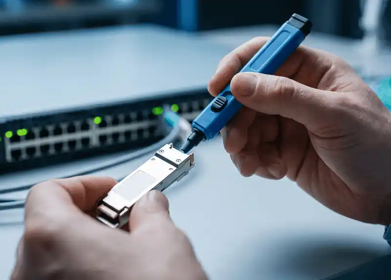
An adapter converter module lets a network port accept a pluggable transceiver of a different form factor. Depending on the product, it may provide mechanical adaptation, electrical lane mapping, module identification, or active interface translation. What it never provides on its own is a working link - that still depends on whether the host platform can expose the interface you need.
Four products cover most of the market: the QSA (QSFP+ to SFP+), the QSA28 (QSFP28 to SFP28), the CFP2-to-QSFP28 converter, and the ODA - an OSFP-to-QSFP adapter, sometimes marketed as an OSFP-to-QSFP-DD adapter, used in 400G and 800G systems.
This guide covers what each one does, which combinations vendors have actually documented, how to qualify a part before you order it, and when an adapter is the wrong tool for the job.

What Is an Adapter Converter Module?
An adapter converter module installs in a host switch, router, network interface card, or transport system port. Its outer shell matches the host cage; inside, a receptacle holds a smaller pluggable module that would not otherwise fit.
The QSA28 is the clearest example. It sits in a QSFP28 port and accepts an SFP28 transceiver, DAC, or AOC. Only one of the four electrical lanes is used - NVIDIA's specification for the MAM1Q00A-QSA28 states that the high-speed channel of the SFP28 receptacle is wired to lane 1 of the QSFP28 connector, and that the three remaining channels are not connected. That single detail explains most of what follows in this guide: three quarters of the port's electrical capacity is simply unavailable.
The Four Things an Adapter Can Do
| Function | What it means in practice |
|---|---|
| Mechanical adaptation | The housing matches the host cage; the internal receptacle retains and aligns the smaller module. |
| Electrical lane mapping | One lane of a multi-lane host port is routed to the contacts of the inserted module. Remaining lanes are usually left unconnected. |
| Module identification | Some adapters carry their own EEPROM. NVIDIA's QSA28 exposes one at I²C address 0x50, selected when the ResetL and ModSelL control signals are asserted. |
| Management pass-through or translation | The host may read the adapter, the inserted transceiver, or both. Passive adapters pass the two-wire bus through; converters bridging different management architectures have to translate it. |
A fifth, less discussed function is thermal. The adapter body sits between a hot optic and the host heatsink, and on high-power modules that interface matters more than the mechanical fit. Adapter datasheets that publish a maximum supported module power are telling you where that limit lies.

What an Adapter Does Not Convert
The word "converter" in the product name is doing a lot of work it has not earned. Unless a datasheet explicitly says otherwise, an adapter will not change fiber type, wavelength, or protocol; it will not make an unsupported port speed appear; it will not turn one port into four usable ports; it will not add breakout capability to a switch that lacks it; and it will not resolve an FEC or auto-negotiation mismatch.
The interface changes only within the electrical and software modes the host already supports. Everything optical - reach, wavelength, connector, whether you need a single-mode or multimode SFP - is decided by the transceiver you insert and by the far end, not by the adapter around it.
Passive Adapters and Active Converters Are Different Products
A passive adapter is essentially controlled PCB trace geometry between the host connector and the inserted module, plus low-speed management components. QSA, QSA28 and most ODA products fall here. Arista, for instance, describes its OSFP-to-QSFP adapter as a passive part.
An active converter contains silicon: a microcontroller, a retimer, a gearbox, or management-interface translation logic. This becomes necessary when the host and the inserted module do not share an electrical generation or a management architecture - which is exactly the CFP2-to-QSFP28 case.
Two adapters with near-identical external dimensions can therefore be entirely different devices. The specifications that distinguish them are the supported host interface, the inserted module type, the management method, the maximum module power, and the list of qualified platforms.
Adapter Module vs Breakout Cable vs Media Converter
These three products get confused constantly, and choosing the wrong one is an expensive mistake to discover at installation time.
| Solution | What it does | Port usage | Right when |
|---|---|---|---|
| Adapter converter module | Lets one host port accept a different form factor | Consumes the whole host port, typically uses one lane | You have exactly one endpoint to connect |
| Breakout cable or optic | Splits a multi-lane port into independent lower-speed links | Uses several host lanes as separate interfaces | Two, four, or eight endpoints share one port |
| Media converter | Converts media, wavelength, or protocol | Separate powered device | Genuine conversion is required, not adaptation |
| Native transceiver | Uses the port as designed | Full port capability | Inventory and platform already match |
The distinction that trips people up most often is the first two. An adapter serves one endpoint and gives up the rest of the port; a breakout serves several and keeps the capacity. If you are weighing a four-way split against four separate adapters, our MPO breakout cable selection guide covers the fiber-side implications of going the breakout route.

The Four Adapter Types in Common Use
QSA: QSFP+ to SFP+ Adapter
A QSA lets a QSFP+ port accept an SFP or SFP+ module or cable. A 40G QSFP+ interface carries four 10G lanes; with a QSA installed, the port operates as a single 10G interface and the adapter connects one lane to the SFP+ receptacle.
NVIDIA's engineering note on the product describes the design intent plainly - a mechanical adapter that fits inside a QSFP port so a single-channel SFP device can be used. The common applications are unglamorous and account for most sales: a 10G server that needs to reach a switch with only QSFP+ ports free, a storage array still on SFP+, an existing 10G optical link that has to survive a 40G switch refresh, or a short SFP+ DAC run to a single appliance.
What a QSA does not give you is four SFP+ connections. For four independent 10G links, use a 40G-to-4×10G breakout. If you are also deciding which optic to put inside the adapter, the differences between SFP and SFP+ modules determine what the host will actually accept.
QSA28: QSFP28 to SFP28 Adapter
A QSA28 puts a 25G SFP28 module, DAC, or AOC into a QSFP28 port. The usual driver is a staged migration: a new 100G top-of-rack switch has to connect to one remaining 25G server, firewall, storage head, or NIC.
The host port must be able to run at 25G through the adapter. A QSFP28 cage plus a QSA28 does not create that capability where the switch hardware or software lacks it, and this is where most QSA28 deployments fail. NVIDIA's own specification lists minimum switch OS and adapter firmware versions for the MAM1Q00A-QSA28 - a reminder that even a passive part has a software dependency.
There is a second, less obvious constraint. Cisco documents that auto-negotiation on-enforce mode is not supported on 10G-QSA and 25G-QSA transceivers across all Nexus platforms. If your standard port template enforces auto-negotiation, a QSA link will not come up until that template is changed - and nothing in the optical readings will tell you why.
Worth confirming before the order goes out: whether the port can present a single 25G interface, whether it belongs to a configurable port group, whether the platform expects a breakout or a dedicated QSA mode, which FEC setting the link needs, and whether the specific SFP28 part number is accepted by the switch.
CFP2 to QSFP28 Converter
CFP2 and QSFP28 both served 100G, but they are architecturally different in a way that matters more than their size difference suggests.
The CFP MSA defines CFP2 management over MDIO, following IEEE 802.3 Clause 45, with physical port address pins and a global alarm pin. QSFP-family modules use a two-wire interface instead. A CFP2-to-QSFP28 product therefore cannot be a passive lane router - something inside it has to bridge MDIO to I²C and map one register set onto another.
That is the single most important question to ask a supplier about this category, and it is answered in the converter datasheet rather than in either MSA. Specifically: does the product include an MDIO-to-I²C bridge, which host electrical interfaces does it support, which register groups are exposed to the host, what is the power ceiling, and how is FEC handled.
A CFP2-to-QSFP28 converter earns its place when a qualified CFP2 platform is still in service, the required QSFP28 optic is cheaper or easier to source, and the converter has been validated against that exact host. Coherent applications add further restrictions around optical mode, management registers, power class, and line-side functionality - a CFP2-DCO port is not a generic 100G client port, and should be treated as a separate qualification exercise.
ODA: OSFP to QSFP-DD and QSFP Adapter
ODA stands for OSFP-to-QSFP-DD Adapter, and it is a vendor term rather than an MSA-defined one. Products sold under this name span a wider range than the acronym implies, which is where the confusion starts.
The OSFP MSA defines OSFP as an eight-lane pluggable form factor supporting up to 400 Gbps (8×50G), 800 Gbps (8×100G), or 1.6 Tbps (8×200G), with the current specification at Revision 5.22. Because OSFP is physically larger than QSFP-DD, an OSFP cage can mechanically accept a smaller QSFP-family module through a purpose-built adapter. The reverse is not possible.
Here is where marketing and platform reality diverge. Many ODA products are advertised as OSFP-to-QSFP-DD adapters carrying 800G or 400G through to the inserted module. But Arista's 800G optics documentation states that OSFP and QSFP-DD are two physically distinct form factors that are not interchangeable, and that the supported adapter for its OSFP ports is the passive ADPT-O-Q-100G, which accepts a 40G or 100G QSFP optic - not a QSFP-DD. The same document adds an operational requirement that is easy to miss: with a QSFP module installed in an OSFP port, the port must be configured for 100G or 40G rather than 400G or 800G.
So before treating an ODA as an 800G part, establish three things separately: the electrical generation of the host port (50G, 100G, or 200G per lane), the lane count the adapter actually wires through, and which QSFP family the switch vendor has qualified in that cage. An 800G OSFP port does not run every QSFP-DD module at every lower rate; the port, the ASIC, the NOS, the adapter, and the module all have to agree on one operating mode. Our QSFP-DD technical overview covers the lane structure on the module side of that equation.
One more boundary: OSFP-XD is a separate specification with sixteen electrical lanes, and the OSFP MSA states that OSFP and OSFP-XD modules are not cross-compatible, with mechanical keying preventing insertion into the wrong port type. An adapter qualified for OSFP is not qualified for OSFP-XD.
On management, both OSFP and QSFP-DD can use CMIS, the Common Management Interface Specification maintained by OIF, which applies across QSFP-DD, OSFP, COBO and QSFP modules over a two-wire host interface. Shared management framing helps, but it does not by itself guarantee that a host will read a module through an adapter.
Adapter Comparison
| Adapter type | Host port | Inserted module | Typical operating result | The check that usually decides it |
|---|---|---|---|---|
| QSA | QSFP+ (or a backward-compatible QSFP port) | SFP / SFP+ | One 1G or 10G link | Whether the port can present a single low-speed interface |
| QSA28 | QSFP28 | SFP28 / SFP+ / SFP | One 25G, 10G or 1G link | FEC setting and auto-negotiation policy |
| CFP2-to-QSFP28 converter | CFP2 | QSFP28 | Qualified 100G client application | Whether MDIO-to-I²C management translation is implemented |
| ODA (OSFP to QSFP / QSFP-DD) | OSFP, 400G or 800G class | QSFP+ / QSFP28 / QSFP-DD, depending on the product | 40G or 100G on documented platforms; higher rates only where the vendor lists them | Which QSFP family the switch vendor has qualified in that cage |
The operating rate comes from the adapter and host documentation, never from the largest number printed on the outer cage.
Documented Compatibility Combinations
Most adapter guides - including the earlier version of this one - tell you to verify support at the platform level and then stop. The table below is a starting point: specific combinations that vendors have published, with the constraint that comes attached and the source you can check it against.
These are documentation entries, not our own lab results. They tell you what a vendor has committed to in writing. They do not substitute for validating the combination on your own NOS release, which is why the last column exists.
| Host platform | Adapter part number | Inserted module | Documented result | Documented constraint | Source |
|---|---|---|---|---|---|
| Arista 800G platforms with OSFP ports | ADPT-O-Q-100G (passive) | 40G or 100G QSFP optic | 100G or 40G link | Port must be configured for 100G or 40G, not 400G/800G. QSFP-DD modules are not covered - OSFP and QSFP-DD remain distinct form factors. | Arista 800G Transceivers and Cables Q&A |
| NVIDIA Spectrum SN2700 switch; ConnectX-4 NIC (QSFP28 ports) | MAM1Q00A-QSA28 | SFP28, SFP+ or SFP transceiver, DAC or AOC | 25G, 10G or 1G link | Only lane 1 of the QSFP28 connector is wired; the other three are unconnected. Minimum switch OS and firmware levels are listed in the specification. Adapter EEPROM at I²C 0x50. | NVIDIA MAM1Q00A-QSA28 product specification |
| Cisco Nexus, all platforms | 10G-QSA and 25G-QSA | SFP+ / SFP28 | 10G or 25G link | Auto-negotiation on-enforce mode is not supported with these adapters. Default FEC varies by optic part number rather than by speed. | Cisco ACI Auto-Negotiation and FEC documentation |
Two patterns are worth extracting. First, every documented combination names a part number on both sides - vendors qualify parts, not form factors. Second, every one carries a configuration requirement that has nothing to do with the adapter itself. That is the pattern to expect from your own platform's matrix.
Seven Checks Before You Order
1. Identify the exact host port
Record the chassis or NIC model, the line card, the port number, the form factor, the NOS version, and the current port-group configuration. "It has a QSFP port" is not a specification - cages that look identical differ in supported speeds, electrical generation, and breakout behaviour, and a part qualified on one line card is frequently not qualified on its successor.
2. Define the link you need, not the adapter you want
Write down one operational speed, one medium, one connector, and one distance. Then check whether the host can actually expose that logical interface. Some platforms split a physical port into several subinterfaces when a lower-speed mode is selected; others keep one interface name and change its operational speed. The difference determines what your configuration and monitoring will look like afterwards.
3. Check port-group and breakout restrictions
High-speed ports are usually controlled in groups, so changing one port can affect its neighbours, the available lanes, or interface numbering. Several platforms also require the same configuration used for a single breakout lane even though only one physical module is installed - which means a QSA can consume a breakout profile you were planning to use elsewhere.
Establish which ports support the mode, whether adjacent ports are affected, whether a reload is needed, and whether unused logical lanes have to be administratively disabled. On some releases, ports left enabled but unconnected generate persistent alarms.
4. Match FEC, auto-negotiation and link training
FEC is the most common cause of a link that comes up on the bench and fails in production, because the correct setting depends on the speed, the cable or transceiver type, and the platform - not on a universal rule.
The granularity is visible in the CLI itself. On Cisco NX-OS, the interface-level FEC options are:
switch(config-if)# fec ?
auto - FEC auto
fc-fec - CL74 (25/50G)
off - turn FEC off
rs-cons16 - RS FEC Consortium 1.6 (25G)
rs-fec - CL91 (100G) or Consortium 1.5 (25/50G)
rs-ieee - RS FEC IEEE (25G)
Six options at one speed, and Cisco's platform documentation lists defaults and exceptions by transceiver part number, including optics on which FEC is disabled by default and line cards that do not support RS-FEC at all. Confirm the minimum FEC the module or cable requires, the configured setting at both ends, and the operational setting at both ends - these three are frequently not the same value.
Disabling FEC or auto-negotiation as a first troubleshooting step is a habit worth breaking. It sometimes produces a link, and it hides the reason the link was failing.
5. Verify EEPROM, coding and DOM behaviour
A mechanically perfect module can still be rejected at insertion, because the host is reading an EEPROM and comparing it against a list.
What you need to know is whether the adapter carries its own EEPROM, whether the host reads the adapter or the inserted transceiver or both, whether the inserted module must carry host-specific coding, and whether DOM values and alarm thresholds are expected to reach the management plane. Nested reporting - a module inside an adapter inside a port - is handled differently by every NOS, and it is common for the host to report the adapter's identity while the optic's diagnostics stay invisible.
With third-party optics, qualify the exact quartet: host, adapter part number, module part number, software release. Changing any one of the four invalidates the result.
6. Check power and thermal headroom
The host has to cool the adapter and the module as one assembly. Compare the maximum module power the adapter supports against the maximum the host port supplies, then account for airflow direction, heatsink type, ambient inlet temperature, and how many adjacent high-power ports are populated.
Thermal problems are late-arriving. A module that passes a five-minute bench test can throttle or flap after an hour of sustained traffic at elevated inlet temperature, and high-power coherent optics should not go into an adapter unless both the host and adapter documentation approve that specific combination.
7. Match fiber, connector and reach
The adapter changes nothing about the optical link. An SFP28 SR optic inside a QSA28 still needs the right multimode fiber, the right connector and polarity, and a distance within its budget; an LR optic still needs compatible single-mode fiber and an acceptable power margin.
Distance limits are where assumptions cost the most - multimode reach varies substantially across OM1 to OM5, and the grade already installed in the building often decides whether a given optic is viable at all. Confirm the fiber type, connector, patch-panel loss, temperature range, and the wavelength compatibility of the far-end transceiver.
A Decision Path for Choosing an Adapter
The checks above establish whether a part can work. This is how to decide whether it should.
Start with the endpoint count. One endpoint points to an adapter. Two or more sharing a single high-speed port points to breakout, and the calculation is rarely close: four adapters mean four consumed ports, four qualification exercises, and four spare parts, against one breakout assembly.
Then ask whether the host exposes the mode you need. If it does not, the decision ends here - no adapter creates a port speed. The alternatives are a NOS upgrade, a different port, a different line card, or a different switch.
If it does, ask what the adapter has to bridge. Matching management architectures on both sides (QSFP-family to QSFP-family, or QSFP-family to SFP-family) means a passive part will normally do, and qualification centres on speed, lane mode, FEC and coding. Mismatched architectures - CFP2 to QSFP28 being the clear case - mean an active converter, and qualification becomes a product-specific project rather than a parts lookup.
Then check the vendor matrix, not the form factor. If your platform's compatibility list does not name the adapter part number, you are the one qualifying it, and that cost belongs in the comparison.
Finally, weigh the port you are giving up. An adapter converts a 100G port into a 25G port for the life of the deployment. Where port capacity is scarce, the adapter that saves money on the transceiver can be the more expensive choice overall.
For anything above a handful of ports, test the production combination rather than a close substitute: production switch model, production software version, adapter part number, module part number, real far-end device, real cable type, intended FEC and port mode. Substituting any element of that list is how validation results stop being predictive.
Where Adapters Fit - and Where They Do Not
Migration points: usually the right answer
A new QSFP28 top-of-rack switch and one server still on an SFP28 NIC is the textbook case for a QSA28, provided the port can present a single 25G interface, the SFP28 or DAC is qualified, the FEC setting matches the NIC, and losing the rest of the 100G port is acceptable. The same logic applies to a QSA reaching a 10G storage appliance from an aggregation switch that has only QSFP+ ports free - an adapter is cheaper and simpler than adding an access switch for one connection.
Reusing QSFP optics in a new OSFP-based switch follows the same shape, with the added step of confirming which QSFP family the vendor supports and configuring the port speed accordingly. Using Arista's documented example, an 800G OSFP port with a QSFP optic behind an ADPT-O-Q-100G is configured explicitly:
switch(config)# interface Ethernet1/1
switch(config-if-Et1/1)# speed 100g-1
The port stops being an 800G port for as long as that adapter is in place. That is not a defect - it is the trade being made, and it should be visible in capacity planning rather than discovered later.
The lifecycle question
Adapters look inexpensive per unit, which is why the total cost tends to be underestimated. Three effects compound at scale.
The first is spares. Every adapter type added to the estate is a new line item, and the meaningful unit is not the adapter but the adapter-plus-module combination that has been validated together. Ten adapter models across three platforms is a materially more complex inventory than a single native transceiver.
The second is qualification. Native transceivers inherit the platform's existing compatibility matrix; adapter combinations often do not, and each NOS upgrade reopens the question for every combination in production.
The third is stranded capacity. A 100G port serving a 25G endpoint carries an opportunity cost that recurs for the life of the switch and, unlike the adapter, never appears on an invoice.
A reasonable dividing line: adapters are efficient for a bounded number of migration points with a known end date. For a permanent deployment measured in hundreds of ports, native modules almost always win once qualification effort and spares complexity are counted.
When to stop and choose something else
An adapter is the wrong tool when four lower-speed endpoints need connecting, when the host has no path to the required mode, when the port group loses more capacity than the saving justifies, when the application needs real media or protocol conversion, when the optic exceeds the thermal limit, when the switch vendor does not support the combination, or when DOM and alarm visibility are operationally mandatory but unavailable through the adapter.
Installation and Validation
Before installing, back up the current port configuration and record existing interface status and error counters - without a baseline, post-installation counters mean very little. Confirm the port mode and the far-end configuration, inspect the adapter and transceiver, clean the optical connectors, and check that airflow and neighbouring ports are unobstructed.
During installation, seat the transceiver in the adapter first and in the correct orientation, then seat the assembly fully in the host cage. A two-part assembly is easier to partially seat than a single module, and a partially seated adapter looks identical to a fully seated one. Never force a latch. Apply the documented port-speed, lane, FEC and negotiation settings before expecting a link.
Afterwards, verify detection, vendor and part-number reporting, administrative and operational speed, FEC status, link state, DOM values where supported, optical power in both directions, error counters, and temperature and power alarms. Then leave it under representative load - a momentary link-up is not validation, and the failure modes specific to adapters (thermal throttling, marginal signal integrity, intermittent management access) all take time to appear. Where you are also running new fiber for the link, our fiber optic cable installation guide covers the cabling side of the same commissioning window.
Troubleshooting Adapter Problems
The adapter is not detected
Likely causes are an unqualified adapter, an incorrect port mode, incomplete insertion, firmware below the documented minimum, or an EEPROM the host does not recognise.
Check the adapter part number against the host support matrix first, since it costs nothing and resolves a large share of cases. Then reseat both parts, try a different port in a different port group, try a known-good adapter, and read the system log rather than only the interface status - rejection reasons usually appear there and not in the interface output.
The adapter is detected but the link stays down
This is the FEC and auto-negotiation zone. Compare configured and operational speed at both ends, then configured and operational FEC at both ends, remembering that admin and operational values diverge routinely. Confirm whether the platform supports auto-negotiation at all through this adapter - as noted earlier, Cisco excludes on-enforce mode with QSA adapters across Nexus platforms, and other vendors have comparable exclusions.
Then check optical power or cable status, test a known-good native transceiver in the same port to isolate the adapter from the port, and review port-group and breakout configuration.
The switch reports an unsupported transceiver
The host is validating something - adapter EEPROM, vendor code, part number, checksum, power class, or application code - and one of those has failed. Use a module coded and qualified for the platform. Override commands exist on most platforms and are best understood as a diagnostic tool rather than a solution, since they typically move the link outside vendor support.
The link flaps or accumulates errors
Candidates are incorrect FEC, marginal signal integrity, unsupported cable length, contaminated connectors, low receive power, excessive temperature, or a firmware or application-mode mismatch.
Compare error counters before and after changing exactly one variable. Replacing the adapter, the optic, the cable and the configuration together will sometimes fix the link and will never tell you why. If receive power sits near the low end of the range, work through the loss budget end to end - our note on insertion loss in fiber networks covers how patch panels and connector pairs accumulate into a margin problem.
DOM data is missing
The link may pass traffic normally with no monitoring data at all, so missing DOM is not by itself an optical fault.
Establish whether the adapter supports pass-through monitoring, whether the host is displaying the adapter EEPROM instead of the inserted module, whether the inserted module supports DOM in the first place, and whether the NOS implements nested module reporting. On several platforms the answer to the last question is simply no, and the correct response is to adjust monitoring expectations rather than to keep replacing hardware.
The module overheats
Work through inlet temperature, fan speed and airflow direction, module power class, adapter power limit, adjacent high-power ports, heatsink contact, and the vendor's derating table. If the margin is genuinely insufficient, the fix is a lower-power qualified optic or a native-form-factor module - improved airflow rarely recovers a design-level shortfall.
Frequently Asked Questions
Does a QSA convert a 40G port into a 10G port?
It lets a QSFP+ host port operate with one SFP+ connection at 10G, provided the host supports that mode. It does not provide four independent 10G ports and it does not add 10G capability to a port that lacks it.
Does a QSA28 convert 100G into 25G?
It lets a QSFP28 port accept one SFP28 module or cable and run at 25G. There is no rate conversion involved - one of the port's four 25G lanes is routed to the module and the other three go unused.
What does ODA stand for?
OSFP-to-QSFP-DD Adapter. It is a vendor naming convention rather than an MSA term, and products sold under it vary: some accept QSFP-DD, others only 40G/100G QSFP. Confirm which QSFP family your switch vendor has qualified before assuming the wider case.
Can an ODA carry 800G through to the inserted module?
Only where the platform documentation says so. OSFP supports 800G as 8×100G, but an adapter's usable rate depends on the lanes it wires through and on what the switch vendor has qualified in that cage. Arista's documented OSFP adapter, for example, requires the port to be configured for 100G or 40G. Treat 800G ODA claims as a question for the host compatibility matrix rather than a property of the form factor.
Is an adapter the same as a breakout cable?
No. An adapter connects one inserted module to one host lane or interface. A breakout exposes multiple host lanes as separate lower-speed connections. The adapter gives up the port's remaining capacity; the breakout uses it.
Does an adapter add latency?
A passive lane-mapping adapter performs no packet processing, so it adds no store-and-forward delay, and its propagation contribution is negligible at these distances. That is not the same as being electrically free - it still introduces insertion loss and affects signal integrity, both of which show up as error rate rather than as latency. Active converters containing a retimer, gearbox, or translation logic do add measurable delay, and the figure belongs in the datasheet.
Can I use any SFP28 module inside a QSA28?
No. The module has to match the far end, the fiber, the reach, the FEC requirement, the temperature range, and the host's coding policy - and the host has to support both the adapter and the target speed.
Will DOM work through an adapter?
Sometimes. Behaviour depends on both the adapter and the host: some systems show the inserted module's diagnostics, some report the adapter, and some offer limited nested visibility. If DOM is an operational requirement, verify it on your platform before ordering rather than after.
Can an OSFP module fit into a QSFP-DD port?
No. OSFP is the larger form factor, and the two are not interchangeable in either direction as modules. Some OSFP hosts accept smaller QSFP-family modules through a qualified adapter; there is no equivalent path the other way.