Product Overview
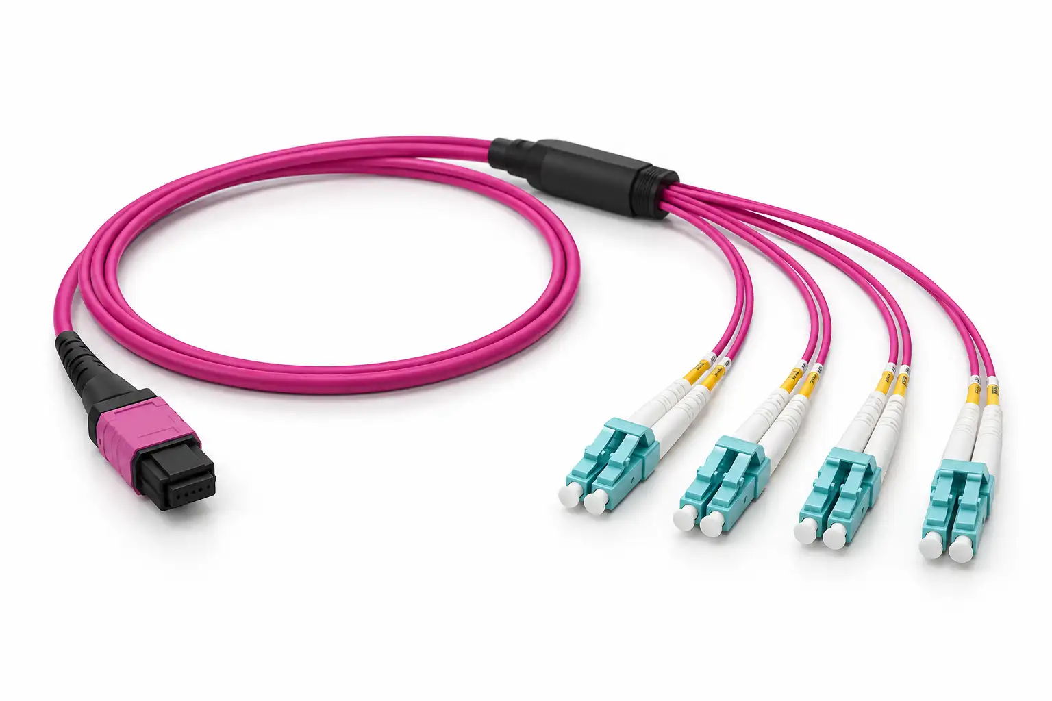
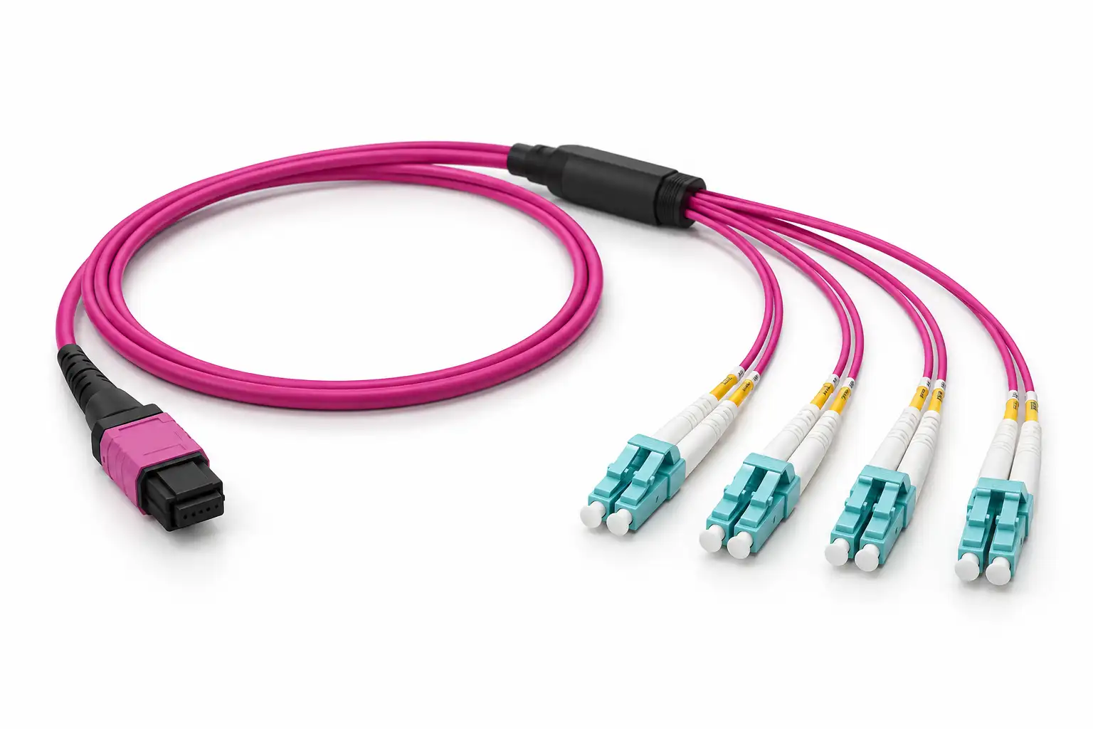
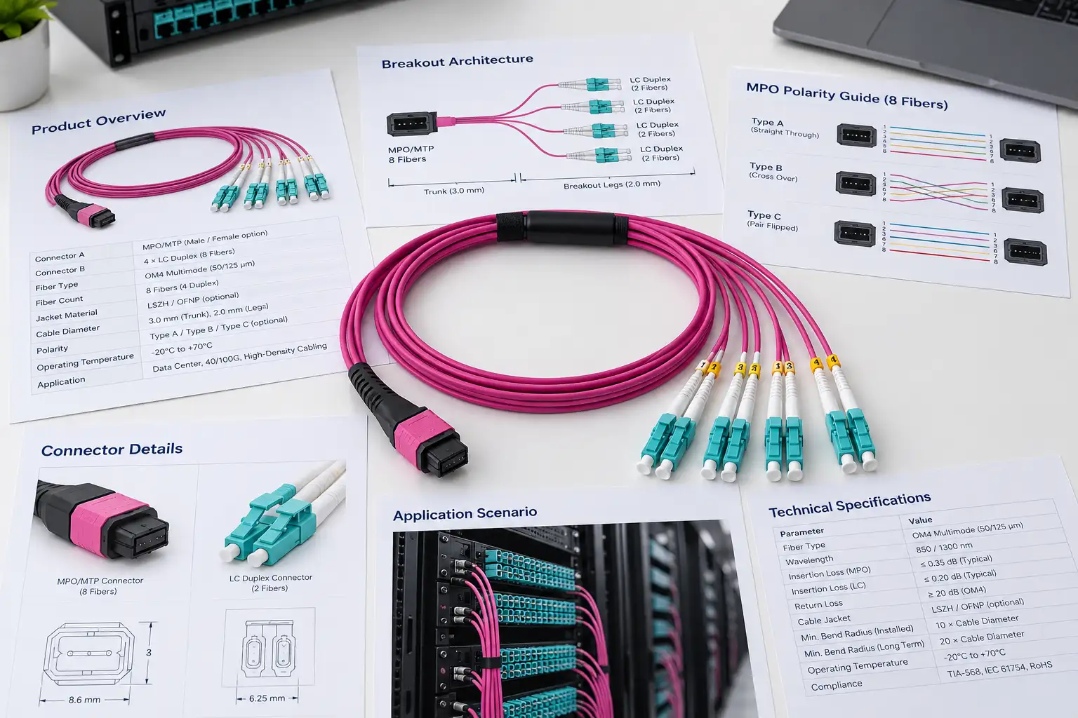
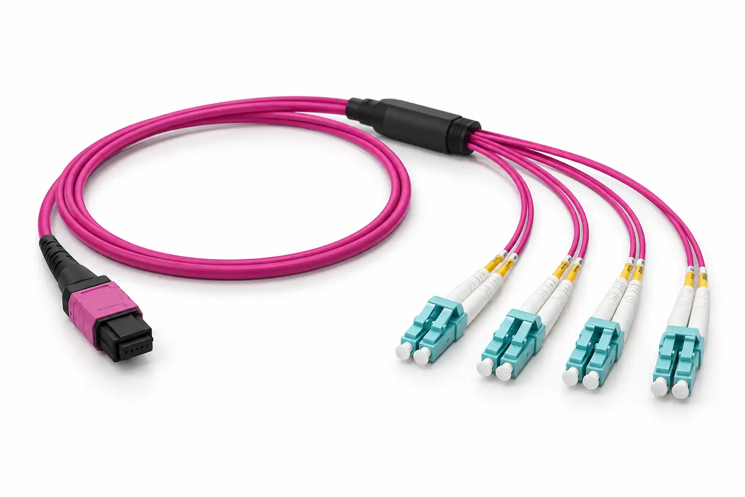
DIMI 8 Fiber MPO/MTP to 4× LC Duplex UPC OM4 Breakout Cable separates one parallel-optics connection into four independent LC duplex links.
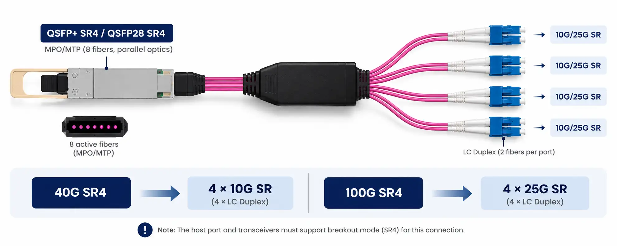
It is intended for equipment-side breakout where an MPO/MTP SR4 interface needs to connect to four duplex optical ports, including compatible 40GBASE-SR4 to 4×10GBASE-SR and 100GBASE-SR4 to 4×25GBASE-SR links.
The assembly uses eight active OM4 50/125 μm fibers. MPO/MTP connector format, gender, polarity, main cable length, LC fanout length, jacket and branch identification can be specified according to the connected equipment.
Active Fiber Count: 8 Fibers
Breakout: 4× LC Duplex
Fiber: OM4 50/125 μm Multimode
LC Polish: UPC
Polarity: Type B / Required End-to-End Mapping
Common Application: Compatible SR4 Port Breakout
Will This Breakout Cable Work With Your Equipment?
This cable is designed for parallel-optics ports that expose four independent transmit and receive lanes. The connected switch, NIC and transceiver must also support the required breakout mode.
A common 40G multimode breakout is:
40G QSFP+ SR4 → MPO/MTP → 4× LC Duplex → 4×10G SFP+ SR
A common 100G multimode breakout is:
100G QSFP28 SR4 → MPO/MTP → 4× LC Duplex → 4×25G SFP28 SR
The cable does not create breakout capability by itself. The host port must support channelized operation, and the optics at both ends must use compatible lane and fiber architectures.
Duplex optics such as LR4, CWDM4 and other wavelength-multiplexed modules use different optical interfaces and should not be assumed compatible with an SR4-style MPO-to-LC breakout.
Check These Items Before Ordering
| Check | Why It Matters |
| Switch / NIC Breakout Support | The high-speed port must support 4-lane breakout or channelization. |
| High-Speed Transceiver | Confirm that the module uses parallel optics such as SR4. |
| MPO/MTP Interface | Confirm the physical connector, fiber population, gender and key orientation. |
| LC-Side Optics | Confirm the four destination transceivers use compatible duplex multimode links. |
| Polarity | Tx and Rx fiber positions must match throughout the complete optical channel. |
| Fiber Type | OM4 multimode fiber should match the installed multimode optics and cabling. |
| Cable & Fanout Length | Length should match the actual rack route and equipment-port spacing. |
Technical Specifications
| Product Type | MPO/MTP to LC Breakout Harness |
| Active Fiber Count | 8 Fibers |
| Breakout Configuration | 4× LC Duplex |
| Fiber Type | OM4 Multimode 50/125 μm |
| MPO/MTP Side | Parallel-Optics MPO/MTP Interface, 8 Active Fibers |
| LC Side | 4× LC Duplex UPC |
| Operating Wavelength | 850 nm / 1300 nm |
| Polarity | Type B / Project-Specific Mapping |
| Connector Gender | According to Required Interface |
| Jacket Options | LSZH / OFNP |
| Jacket Color | Magenta / Custom |
| Main Cable Length | Custom |
| LC Fanout Length | Custom |
| Branch Identification | LC01–LC04 / Custom Labels |
8-Fiber Breakout Structure & Polarity
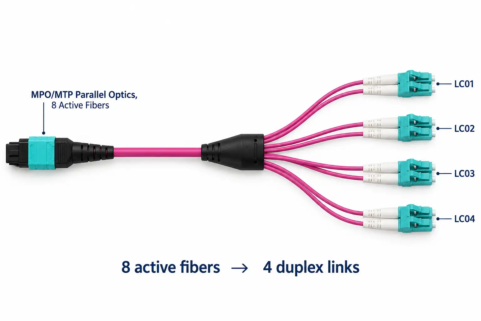
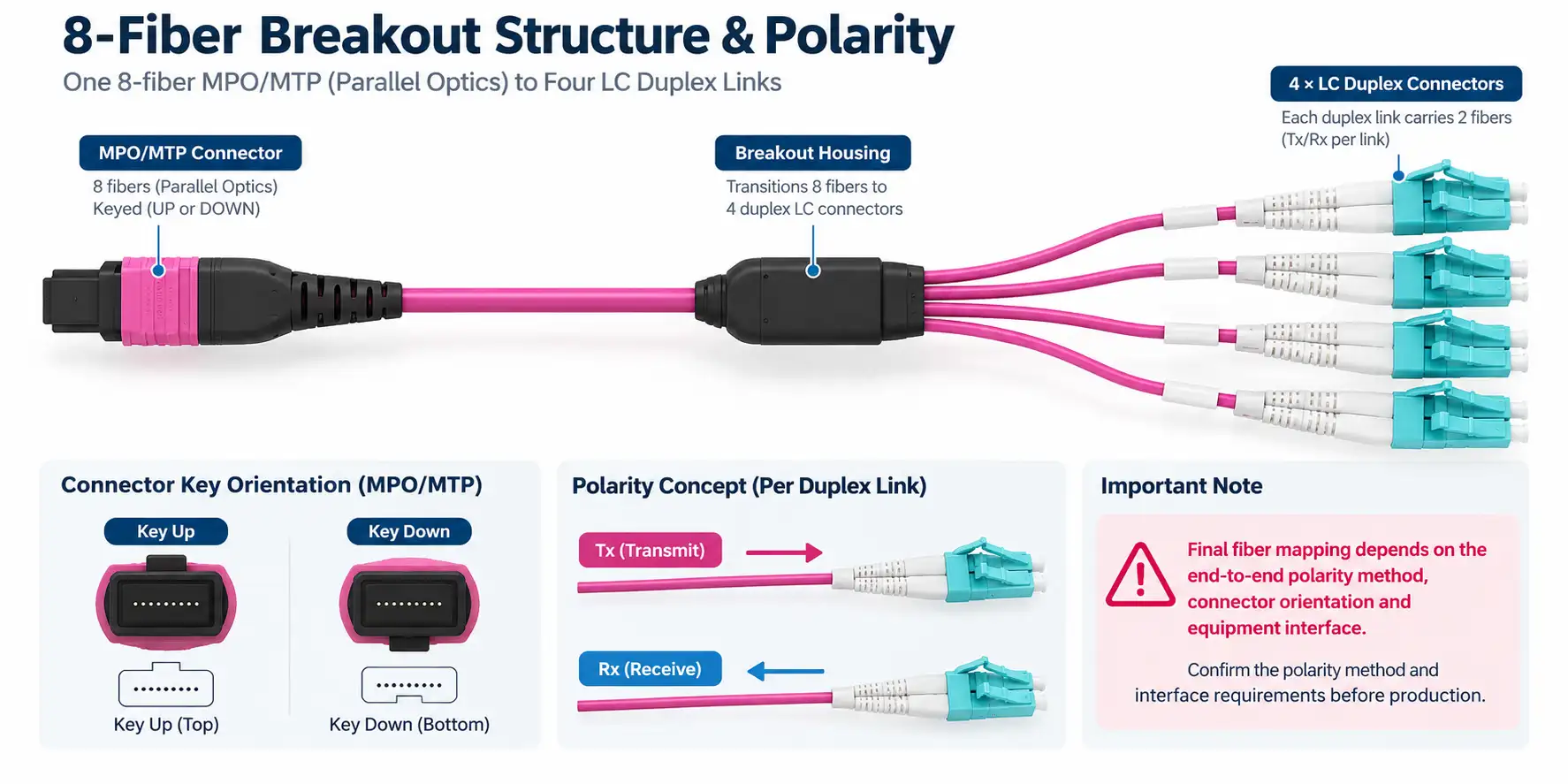
An SR4 link uses four transmit lanes and four receive lanes. The breakout harness separates these eight active fibers into four LC duplex branches.
Each LC duplex branch becomes one independent two-fiber optical path to a lower-speed transceiver.
Active Fibers: 8
Parallel Optical Lanes: 4
LC Duplex Links: 4
The physical MPO/MTP connector should be selected according to the transceiver and installed cabling system. Many SR4 modules use an MPO-12 interface with eight active fiber positions, while Base-8 cabling systems may use an 8-fiber MPO/MTP format.
Do Not Select Polarity From the Cable Name Alone
Type B is commonly used for parallel-optics breakout links, but the correct Tx/Rx mapping depends on the complete channel.
Connector key orientation, MPO/MTP gender or pinning, adapters, patch panels and the connected transceivers all affect the required mapping.
If the existing cabling polarity is not known, provide the switch model, transceiver part numbers or a simple connection diagram before production.
Common Breakout Applications


Configuration Information for Quotation
| Information | What to Provide |
| Switch / NIC | Model or Port Information |
| High-Speed Optic | QSFP+ / QSFP28 Transceiver Part Number |
| LC-Side Optics | SFP+ / SFP28 Transceiver Part Number |
| MPO/MTP Interface | Connector Format and Gender |
| Polarity | Type B or Required End-to-End Mapping |
| Cable Length | Required Main Cable Length |
| Fanout Length | Required LC Branch Length |
| Jacket | LSZH / OFNP |
| Branch Labels | LC01–LC04 / Custom |
| Quantity | Project Quantity |
FAQ
Q: Can this cable be used for 40G to 4×10G breakout?
A: Yes, when the 40G port uses compatible parallel 40GBASE-SR4 optics and the switch supports four-lane breakout. The four LC branches can then connect to compatible 10GBASE-SR optics.
Q: Can it be used for 100G to 4×25G breakout?
A: Yes, a compatible 100GBASE-SR4 QSFP28 link can be broken out to four 25GBASE-SR SFP28 links when the host port supports the required 4×25G breakout mode.
Q: Does every 40G or 100G optical module support this breakout?
A: No. The transceiver must use a compatible parallel-lane architecture. Modules that use duplex LC wavelength multiplexing, for example, do not use the same MPO-to-4×LC breakout method.
Q: Do I need an 8-fiber MPO or an MPO-12 connector?
A: SR4 links use eight active fibers, but the physical connector format depends on the optical module and cabling system. Many QSFP+ and QSFP28 SR4 transceivers use an MPO-12 interface with eight active positions, while Base-8 cabling systems may use an 8-fiber MPO/MTP format. Confirm the equipment interface before ordering.
Q: Which polarity should I order?
A: Type B is common in parallel-optics breakout links, but the correct mapping depends on the complete channel. Confirm MPO/MTP orientation, gender, adapters and the connected optics before finalizing the cable.
Related MPO/MTP Resources
MTP MPO Fiber Breakout Cable - Compare MPO-to-LC and MPO-to-MPO breakout configurations.
MPO Breakout Cable Guide - Fiber count, polarity, MPO gender and breakout-leg selection.
16 Fiber MPO-16 to 8× LC Duplex OM4 Breakout Cable - A higher-fiber-count MPO-to-LC breakout configuration for other parallel-optics architectures.
MPO Data Center Cabling Design Guide - Plan fiber count, connector format and MPO cabling architecture for high-speed links.
Need an MPO-to-4×LC Breakout Cable for Your Equipment?
Send the switch or NIC model, transceiver part numbers, MPO/MTP interface, required polarity, cable length, LC fanout length, jacket and quantity.
If the breakout configuration is not yet confirmed, include the high-speed port and the four destination optics so the connector format and fiber mapping can be checked before production.
Hot Tags: MPO to 4 LC duplex breakout cable,8 fiber MPO breakout cable,MTP to 4 LC duplex cable,OM4 MPO to LC breakout cable,MPO to LC breakout harness,40G to 4x10G breakout cable,100G to 4x25G breakout cable