
Product Overview
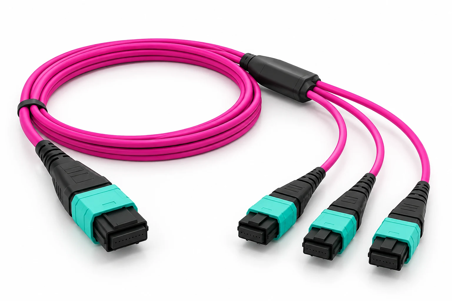
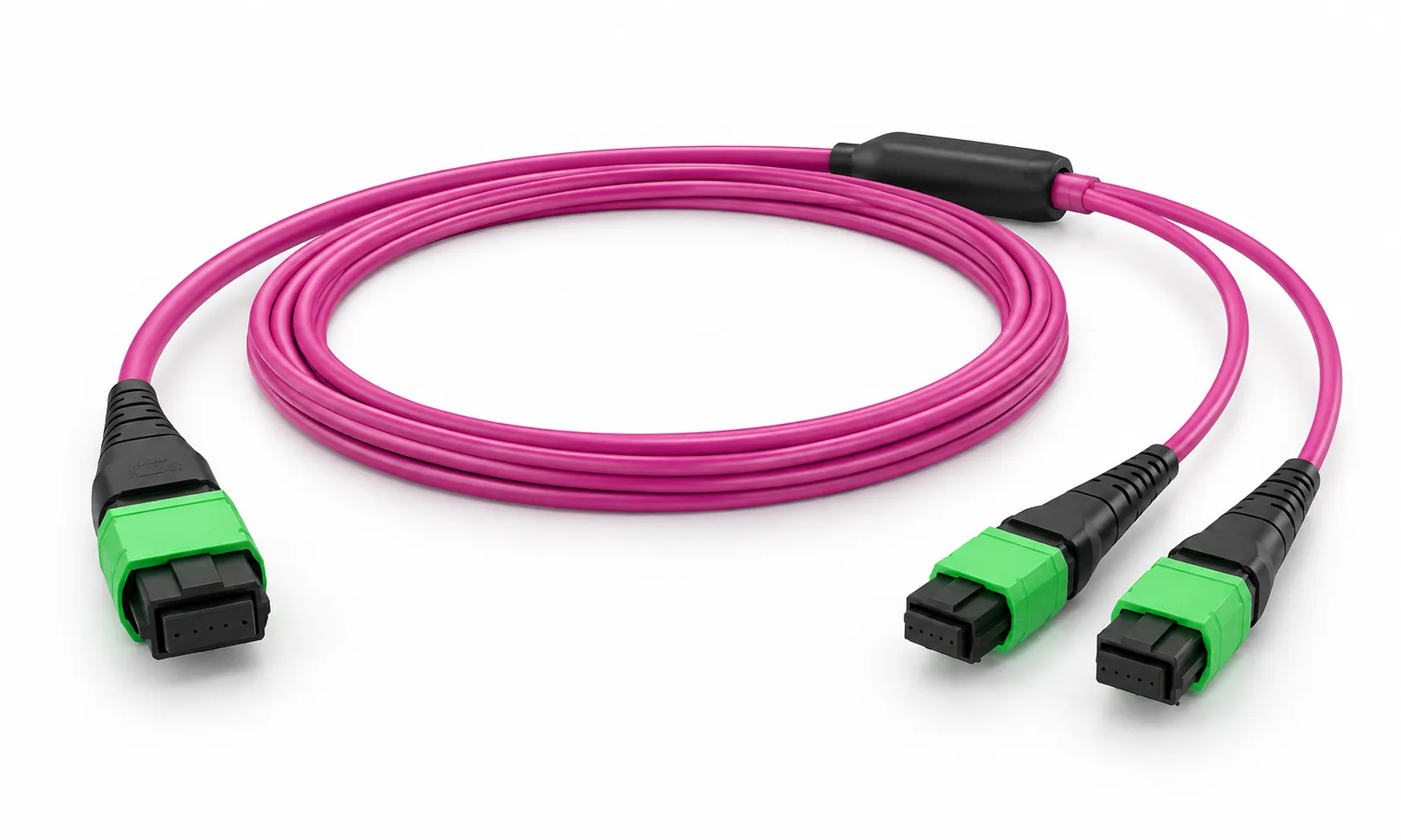
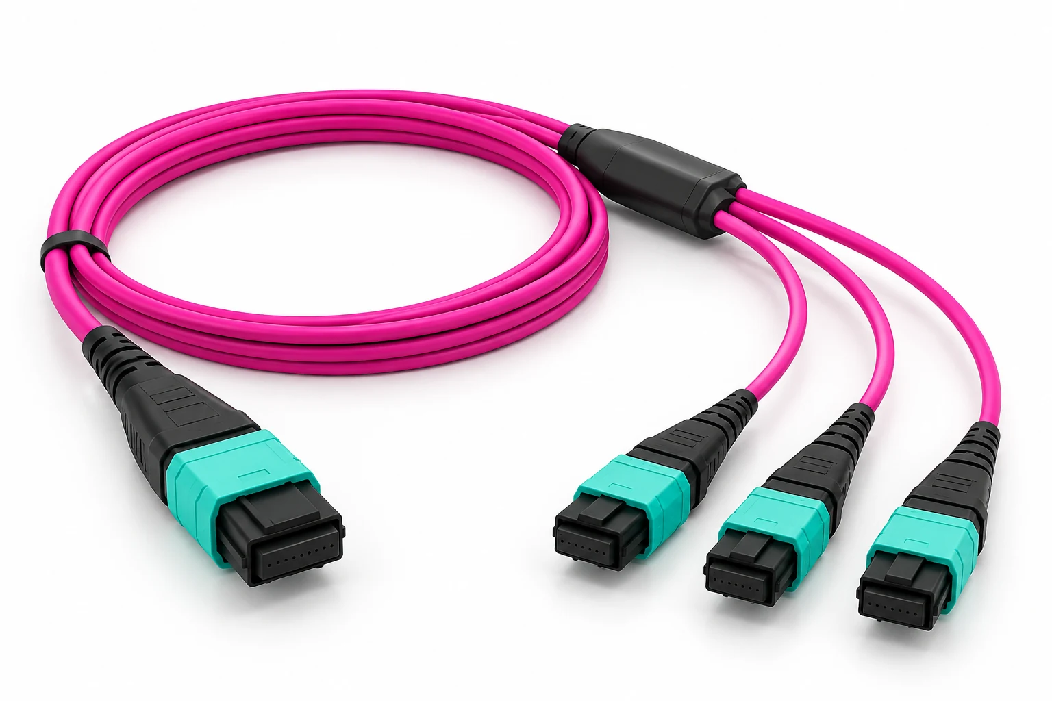
DIMI 24 Fiber MPO-24 UPC to 3× MPO-8 UPC OM4 Breakout Cable redistributes one 24-fiber high-density MPO interface into three independent 8-fiber MPO links. It is designed for Base-24 to Base-8 conversion, structured cabling migration and high-density data center fiber distribution.
Built with OM4 50/125 μm multimode fiber, the assembly keeps all twenty-four fibers in service by dividing them into three complete 8-fiber groups. This provides a direct MPO-to-MPO conversion path for existing Base-24 backbone capacity that must feed Base-8 equipment-side or distribution links.
Fiber Count: 24 Fibers → 3×8 Fibers
Fiber Type: OM4 Multimode 50/125 μm
Connector A: 1× MPO-24 / MTP-24 UPC
Connector B: 3× MPO-8 / MTP-8 UPC
Polarity: Type B / Project-Specific Mapping
Typical Use: Base-24 to Base-8 migration and 40G/100G parallel-optics cabling
Why Choose an MPO-24 to 3× MPO-8 Conversion Cable?
Full 24-Fiber Utilization
Twenty-four fibers are redistributed into three complete 8-fiber branches, avoiding unused fiber positions in the conversion path.
Base-24 to Base-8 Migration
Reuse existing MPO-24 backbone capacity while presenting three 8-fiber links to newer Base-8 network infrastructure.
MPO-to-MPO Conversion
The assembly maintains multi-fiber connectivity from trunk to breakout branches without introducing LC or SC transition connectors.
Project-Specific Configuration
Connector gender, polarity, branch sequence, cable length, jacket and identification can be matched to the installed topology.
24F to 3×8F Breakout Structure
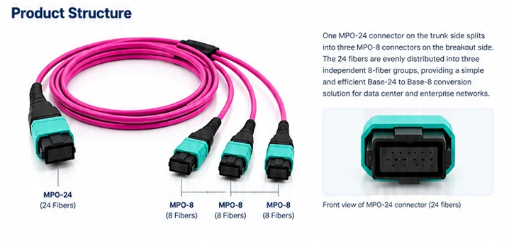
One MPO-24 connector carries twenty-four multimode fibers in a single high-density interface. The breakout assembly separates that fiber count into three independent MPO-8 branches, with eight fibers assigned to each branch.
This structure is useful when a Base-24 trunk or distribution link must interface with multiple Base-8 paths. Because the conversion remains MPO-to-MPO, it preserves a compact multi-fiber cabling architecture through the transition.
Trunk Side: 1× MPO-24 / MTP-24 UPC
Breakout Side: 3× MPO-8 / MTP-8 UPC
Branch A: 8 Fibers
Branch B: 8 Fibers
Branch C: 8 Fibers
24F to 3×8F Fiber Mapping
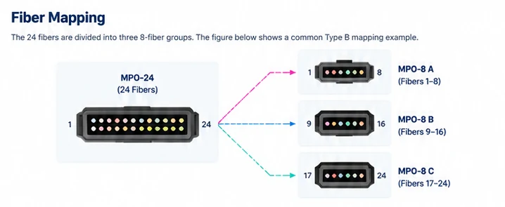
The twenty-four fiber positions are divided into three 8-fiber groups so that each breakout connector receives a complete Base-8 channel set.
Branch A: Fibers 1–8
Branch B: Fibers 9–16
Branch C: Fibers 17–24
Final polarity and lane orientation should match the end-to-end cabling design. Type B is commonly used in parallel-optics conversion assemblies, while project-specific mapping can be defined for existing patch panels, cassettes or equipment interfaces.
Technical Specifications
| Product Type | MPO/MTP Breakout / Conversion Cable |
| Fiber Count | 24 Fibers → 3×8 Fibers |
| Fiber Type | OM4 Multimode 50/125 μm |
| Connector A | 1× MPO-24 / MTP-24 |
| Connector A Polish | UPC |
| Connector B | 3× MPO-8 / MTP-8 |
| Connector B Polish | UPC |
| Connector Gender | Female / Male Options |
| Polarity | Type B / Project-Specific Mapping |
| Operating Wavelength | 850 nm / 1300 nm |
| Cable Structure | 1×24F → 3×8F |
| Jacket | LSZH / OFNP Options |
| Jacket Color | Magenta / Custom |
| Main Cable Length | Custom |
| Breakout Leg Length | Custom |
| Typical Application | Base-24 to Base-8 conversion, 40G/100G cabling and structured network migration |
Why Convert 24 Fibers into Three 8-Fiber Links?
Many high-density structured cabling systems use MPO-24 to consolidate backbone fiber capacity, while common parallel-optics equipment paths use groups of eight active fibers. A 24-to-3×8 conversion assembly bridges those two architectures without leaving part of the 24-fiber link unused.
This approach is particularly useful when an installed Base-24 backbone needs to support multiple 8-fiber channels for 40G/100G SR4-class connectivity, rack-level distribution or network migration.
The result is a simple conversion path: one 24-fiber trunk → three independent 8-fiber links.
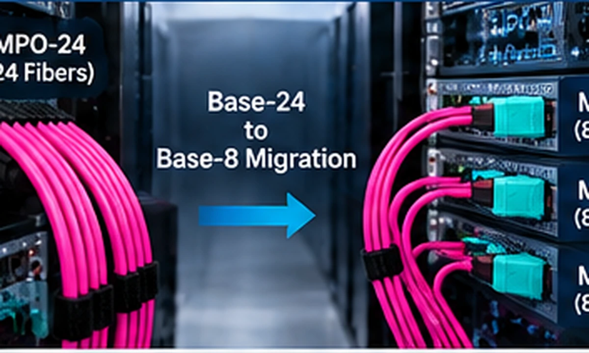
Typical Applications


How to Specify Your MPO-24 Conversion Cable
| Requirement | Example |
| Fiber Type | OM4 50/125 μm |
| Configuration | 1× MPO-24 → 3× MPO-8 |
| Connector A | MPO-24 UPC Female |
| Connector B | 3× MPO-8 UPC Female |
| Polarity | Type B |
| Main Length | Project Length |
| Breakout Length | Project Length |
| Jacket | LSZH / OFNP |
| Branch Labels | A / B / C or Customer Label |
| Quantity | Project Quantity |
FAQ
Q: What does an MPO-24 to 3× MPO-8 conversion cable do?
A: It redistributes the twenty-four fibers from one MPO-24 interface into three separate 8-fiber MPO links, allowing a Base-24 cabling system to connect to Base-8 paths.
Q: Why use 3× MPO-8 instead of 2× MPO-12?
A: Three MPO-8 branches align the twenty-four fibers into three complete 8-fiber groups, which is useful when the downstream cabling architecture is based on 8-fiber parallel-optics links.
Q: Is this cable suitable for 40G and 100G networks?
A: It can be used in compatible multimode parallel-optics cabling systems where 8-fiber links are required. The transceiver interface, polarity and end-to-end topology should be confirmed before deployment.
Q: What polarity is commonly used?
A: Type B is a common configuration for MPO conversion assemblies, but the final fiber mapping should match the installed cabling system and connected equipment.
Q: Can connector gender and branch length be customized?
A: Yes. Connector gender, polarity, main cable length, breakout-leg length, jacket and branch identification can be specified for the project topology.
Q: Does the conversion use all 24 fibers?
A: Yes. The 24 fibers are divided into three groups of eight, allowing all fiber positions to be assigned to the three MPO-8 branches.
Related MPO/MTP Resources
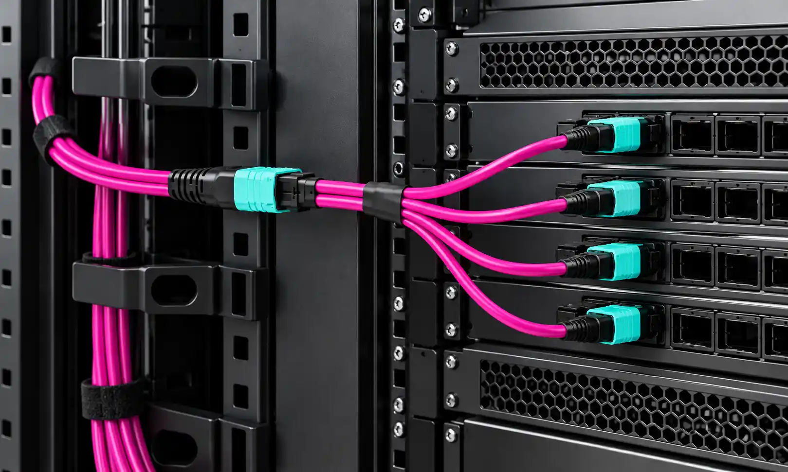
MTP MPO Fiber Breakout Cable - Explore DIMI breakout and conversion configurations for high-density multi-fiber cabling.
MPO Data Center Cabling Design Guide: 40G–800G - Understand how fiber count, connector structure and polarity affect high-speed cabling architecture.
MPO Connectors for 400G and 800G - Compare MPO-8, MPO-12, MPO-16 and higher-density interface structures.
Need an MPO-24 to 3× MPO-8 Cable for Your Project?
Send the existing MPO backbone configuration, connector gender, polish, polarity, required main cable length, breakout-leg length and quantity. DIMI can configure the MPO-24 to three MPO-8 branches around the actual Base-24 to Base-8 cabling topology.
Hot Tags: mpo-24 to 3× mpo-8 om4 breakout cable | 24 fiber, China mpo-24 to 3× mpo-8 om4 breakout cable | 24 fiber manufacturers, suppliers, factory